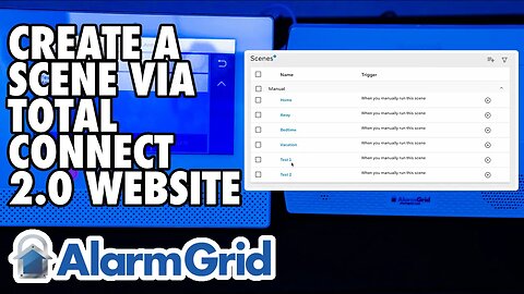
Total Connect 2.0 - Creating a Scene via Website
In this video, Dylan from Alarm Grid shows you how to create a scene in Total Connect 2.0 using the website at www.totalconnect2.com. Start by logging into the page using your TC2 credentials. Once you've logged in, follow these steps to create a scene.
From the menu on the left, choose Scenes. If you have the menu minimized, you'll just see an icon with a movie clapperboard rather than the word Scenes. When you first enter scenes, you'll see some scenes that exist by default within TC2. You are free to customize any of these scenes you like, but for demonstration purposes, we're going to choose the Add Scene button at the upper right. It looks like a hamburger menu with a + symbol next to it.
The first step is to choose a name for the scene. The name you choose should help you to remember what the scene will do. The scene name will hold up to 15 characters. Next, choose when the scene will trigger. This can be based on a schedule, based on the state of a security system device, or by manually triggering the scene.
If you choose to run at a scheduled time, you can choose a specific time, and then you can choose to repeat at the same time on subsequent days. You could choose 8:00 PM and then repeat every day, Monday - Friday. This setup will repeat on the selected days until you make a change to the scene or delete it. You also have the options of Sunrise and Sunset, which will occur based on the zip code for the system.
If you choose to activate the scene based on a security system device, you'll choose which device, and what state causes the scene to run. It could be arming or disarming of the security system itself that triggers the scene, or a fault on a particular device. It can also be based on another automation device, such as a door lock being locked or unlocked that causes the scene to run. Manually means that you will manually trigger the scene either through the panel touchscreen or through the TC2 app or webpage. Once you choose a trigger, click "Continue".
Next, you'll choose the scene's action. This is what you want to automate when the trigger occurs. In our example, we have a Z-Wave device listed under "Others" and we have the security system that is available to act once our trigger occurs. The options you will see here depend on the number and type of automation devices you have in your system. If you have Z-Wave locks, you'll have a section titled Locks. If you have lights, you'll have a section titled Lights. Our device is a switch/outlet, so it shows up under the title Other.
In our example, we want to set the switch to turn on when we manually run the scene. So, we hit the dropdown for Other and select the Switch by clicking on it, this will put a checkmark in the box by the device name. Then, we want to toggle the icon to On. This means when this scene runs, it will turn on the switch. This is the only action we want to include, so next click "Continue" in the lower right.
You'll be provided with a summary screen showing you the programming you've selected. If anything is wrong, or you want to add to the scene, you can click the "Edit" button in the lower right. Otherwise, click "Save". This saves your work. Now you can test the scene by manually running it. You can run the scene from the main "Scenes" screen by clicking the right-arrow to the right of the scene name. If you are using a touchscreen panel, such as a Lyric system, you will also have an option to manually run the scene through the touchscreen once the panel and Total Connect 2.0 have synced.
https://www.alarmgrid.com/faq/how-do-i-create-a-scene-in-total-connect-2-0-via-website
http://alrm.gd/get-monitored
4
views
LynxTouch - Automate Arming Using A Z Wave Lock
In this video, Darrell from Alarm Grid shows you how to automate the arming of a LynxTouch panel based on the locking of a Z-Wave door lock. This video assumes the Z-Wave door lock has already been included into the system. Bear in mind, when you enable this feature, it will automatically arm your system in the selected mode every time the Z-Wave door is locked.
From the Home Screen of the LynxTouch panel, go to Automation - Arrow Down - Tools - Advanced Tools - Enter Installer Code (default is 4112). This will bring you to the Advanced Tools Menu. From here, choose "Locking Door". By default, the Z-Wave Locking Door feature shows Disabled. By pressing on the word Disabled, you can toggle through options for Arm Stay, Arm Away, or Arm without Auto Stay.
The option to Arm without Auto Stay means that when you lock the Z-Wave Lock, the system will Arm Away, and it will remain in the Away mode, even if the system doesn't see an entry/exit door fault and restore (open and close) during the exit delay (as though someone walked out the door).
Auto Stay Arming is a false alarm reduction feature meant to change the arming mode in the event that you accidentally armed away, when you meant to arm stay. You might choose this option if you want to Arm Away when the Z-Wave lock is locked, but perhaps you don't have any doors that are set for the entry/exit zone type. Seeing an entry/exit zone open and close during the exit delay is how the system can tell that someone left the premises. If the system doesn't see that, it will assume you didn't leave and that you accidentally armed in the wrong mode.
Once you select the option you want, be sure to hit the Save button at the lower right, then you can hit the return arrow at the top right until you're back at the Home screen.
https://www.alarmgrid.com/faq/how-do-i-automate-arming-with-z-wave-locks-on-lynxtouch
http://alrm.gd/get-monitored
3
views
Qolsys IQ Panel 4 - Bypassing a Sensor
In this video, Dylan from Alarm Grid shows you how to manually bypass, as well as auto-bypass, a sensor on a Qolsys IQ Panel 4. By default, the auto-bypass option is enabled. This means that if you attempt to arm your system while a burglary zone is faulted, the system will automatically bypass the faulted zone and arm any unbypassed burglary zones. This will happen regardless of how you arm, locally at the panel, via a key fob, or remotely using Alarm.com
The auto-bypass option is enabled or disabled by pressing the gray tab at the top of the home screen, choosing Settings - Advanced Settings, entering the Installer or Dealer Code (1111 or 2222 respectively, by default), then going to Installation - Security and Arming. You can scroll down to find the Auto-bypass option, or you can type bypass in the search bar at the top of the screen to bring it up automatically. If you disable this option, you will not be able to arm remotely if any burglary zone is faulted at the panel at the time you want to arm. There is no option to manually bypass zones through Alarm.com.
To manually bypass one or more burglary zones from the panel touchscreen, go to the arming screen, click the right-pointing arrow, if necessary, then in the list of zones, select "All" rather than "Active". This will show you all zones, rather than just the active or faulted zones. Click on each zone you wish to bypass. The zone will show a checkmark to the left when it has been selected. Once all zones you wish to bypass have been selected, arm the system. Selected zones will be bypassed until the system is disarmed. Once disarming occurs, all bypassed zones will automatically be unbypassed.
Life safety zones such as smoke detectors and carbon monoxide detectors cannot be bypassed under any circumstances.
https://www.alarmgrid.com/faq/how-do-i-bypass-a-sensor-on-the-qolsys-iq-panel-4
http://alrm.gd/get-monitored
20
views
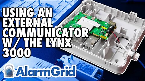
Lynx L3000: Connecting an External Communicator
In this video, Darrell from Alarm Grid shows you how to connect an external communicator to a LynxPlus or L3000 panel from Honeywell. There are communicators that are made to work with the L3000 that can be installed inside the panel plastic and are hidden from view. However, those communicators are no longer available, so if you have an L3000 and you wish to upgrade it to an LTE communicator, this is how you do it.
IMPORTANT NOTE: The L3000 can support Total Connect 2.0, however, the LTEM-PA and LTEM-PV communicators will not support TC2 with the L3000 panel. So, if you plan to use Total Connect 2.0, you'll want to choose a communicator other than the LTEM-P Series. The connections will be similar, regardless of which external communicator is used.
Before you begin, be sure that both the L3000 and the communicator are powered down. This will involve unplugging their respective plug-in power supplies, and backup batteries. Once you're sure both pieces of equipment are powered down, continue.
In order to make the proper connections, you will need an LYNXGSMEXTCB wiring harness. These are no longer available from the manufacturer, but you may be able to find one on eBay or a similar market. The LYNXGSMEXTCB plugs into a modular port on the L3000 main board. Depending on the version of the panel, the port is either located at the upper right side (when the panel is opened) of the board, near the hinges that connect the front of the panel to the back. Or it is located on the right side of the board as shown in this video. The cable has a keyed header, so it will only plug in using the correct orientation.
Once the cable has been connected to the panel, route the wires through the wiring access in the back. Now turn your attention to the communicator. Open the communicator and route the wires from the LYNXGSMEXTCB to the communicator through any available wiring access. In this video, we use the wiring port at the bottom of the LTEM-P Series communicator, but different communicators will have different wiring access channels. Just be sure to route the wire so that both the panel and the communicator covers can be closed properly to prevent any tamper warnings.
Because the communicator will need to use its own transformer, only three (3) wires from the L3000 panel will connect to the communicator. These are the Data In, Data Out, and Ground wires. Due to a quirk in the way the L3000 and the LYNXGSMEXTCB are made, the Black wire is actually DC Positive (+) and the Red wire is actually DC Negative (-). This means that you will not use the Black wire from the harness.
On the LTEM-P Series communicator, connect the Green wire from the L3000 to the terminal marked RX. Connect the Yellow wire to the terminal marked TX, and connect the Red wire to the terminal marked GND. If you are using a different communicator just remember that the Green wire will go to ECP Data In on the communicator, and the Yellow wire will go to ECP Data Out with the Red wire from the harness on the L3000 going to the communicator GND terminal. For full instructions, see the FAQ: https://www.alarmgrid.com/faq/how-do-i-use-an-external-communicator-with-a-lynx-l3000.
Once the wiring is completed, you can power up each device based on the instructions for that device. Connect the communicator's battery, then plug in its DC power adapter. Connect the battery to the L3000, then plug in its transformer. To register the communicator, contact your alarm dealer.
https://www.alarmgrid.com/faq/how-do-i-use-an-external-communicator-with-a-lynx-l3000
http://alrm.gd/get-monitored
7
views
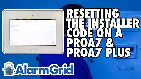
PROA7 or PROA7PLUS - Resetting the Installer Code
In this video, John from Alarm Grid shows you how to edit the Installer Code in a Resideo/Honeywell Home PROA7 or PROA7PLUS alarm panel. To do this, you will need to know the current Installer Code. Alarm Grid usually recommends that you leave the Installer Code set to the default. This is because if you forget the Installer Code, there is no back door into programming. A monitored panel can be edited using the AlarmNet360 page, but an unmonitored panel with an unknown Installer Code can't be programmed. The Installer Code cannot disarm the panel if it has been quick-armed, or armed with any other user code.
To edit the Installer Code, from the Home Screen of the panel, press the hamburger menu icon in the bottom-center of the screen. This will bring up a list of menu options including Favorites, Devices, Sensors, Cameras, Scenes, Events, Settings, Tools, and Help. To see all of the options, you will. need to place your finger on the list and slide up to scroll through it. To change the Installer Code, scroll toward the bottom and select Tools. When prompted, enter the current Installer Code. The default is 4112.
This will bring you to the Installer's Menu. Here you'll see System Information, System Tests, Programming, Local Alarm Mode, WIFI Touchscreen enrollment, Installer PIN, and Default Options. Once again, you'll have to scroll up and down with your finger to see all of the available choices. Tap the Installer PIN option. This will bring you to the screen where you can review the current Installer PIN, or change it. By default, the 4-digit PIN is hidden. There is a "SHOW" button to the right that you can click to review the current PIN. Of course, you know what that PIN is because you had to use it to get to this screen.
Press Change Installer PIN. You'll be provided with a number pad and asked to "Enter new PIN". Once you key in the new 4-digit PIN, you'll be asked to "Confirm new PIN". Enter the same 4-digit PIN again. You'll be returned to the previous screen and a message will show at the top advising that the "PIN has successfully been changed". Press the left-arrow button in the upper left of the screen repeatedly until you return to the home screen.
https://www.alarmgrid.com/faq/how-do-i-reset-the-installer-code-on-a-proa7-or-proa7plus
https://www.youtube.com/watch?v=nlf8PD0om00
2
views
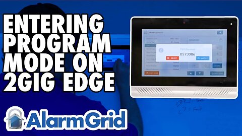
2GIG Edge: Entering Programming Mode
In this video, John from Alarm Grid shows you how to enter programming on a 2GIG Edge system. The 2GIG Edge is a 7" all-in-one color touchscreen system with WIFI and cellular communicators built in. It has a Z-Wave Plus V2 controller.
To enter programming, press the settings icon. This looks like a gear and is located on the lower right side of the Home screen. When prompted, enter the Installer Code. The default Installer Code is 1561. If you enter the Master Code instead of the Installer Code, you will enter the Master User menu, which offers different options, but panel programming will not be accessible from the Master User menu.
After entering the Installer Code, you'll be taken to the Installer's Menu. You may notice you have some of the same options given in the Master User menu, but there will be a number of options here that you don't see when you enter using the Master Code. Scroll down to the bottom row of the presented options. Press the Installer Toolbox icon. This brings you to the sub-menu containing Panel Programming.
Within the Panel Programming Menu, you will see options for Wireless Zones, Built-in Zones, Keyfobs, Keypads, Image Sensors, Network Settings, and Advanced Settings. Go through each menu option until you have configured your panel. In most cases, settings are saved automatically as you go (unless you see a Save button, which means you should manually save your work).
To exit programming, you can press the back arrow at the upper right side of each screen until you completely exit. You can also press the House icon in the lower right to return to the main screen.
https://www.alarmgrid.com/faq/how-do-i-get-into-programming-on-my-2gig-edge http://alrm.gd/get-monitored
https://www.youtube.com/watch?v=0Um6EdSwhaY
7
views
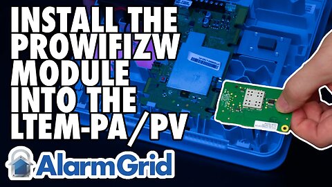
LTEM-PA/LTEM-PV: Install PROWIFI or PROWIFIZW
In this video, Julia from Alarm Grid shows users how to install the PROWFI or PROWIFIZW into an LTEM-PA or LTEM-PV communicator. The first thing you should do is power the system down by unplugging the DC power adapter and then removing the cover and unplugging the battery.
To remove the cover, use a small screwdriver to press in the locking tabs on the bottom edge of the LTEM-P communicator, and then pull the cover up, or forward and lift it out of the way. Now you can unplug the positive lead for the battery to power the device completely down. All of the LEDs on the unit should be off.
The PROWIFI or PROWIFIZW installs in the upper left corner of the main communicator board. There is a piece of foam tape on the back of the communicator. Be sure to leave this in place. If the LTEM-P series communicator has a piece of foam on the plastic, one that will be located beneath the PROWIFI or PROWIFIZW after it's installed, this piece of foam should be removed.
Line the edge connector of the LTEM-PA or LTEM-PV up with the port on the back of the PROWIFI or PROWIFIZW. There is a plastic locking tab located on the LTEM-P communicator that the board of the PROWIFI will snap under when it's installed correctly. Once the board is lined up with the connector, slide it forward until it snaps into place on the edge connector. The PROWIFI or PROWIFIZW will be held in place by the connector on the back, and by the plastic locking tab at the top.
Plug in the DC power adapter, plug in the battery, and replace the communicator's cover. The communicator should power up and be ready to activate.
https://www.alarmgrid.com/faq/how-do-i-install-the-prowifizw-in-a-ltem-pa-or-ltem-pv
http://alrm.gd/get-monitored
2
views
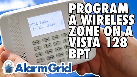
VISTA 128BPT - Programming a Wireless Zone
In this video Griffin from Alarm Grid shows the user how to program a wireless receiver and then a wireless zone into a VISTA-128BPT panel. The steps to program a VISTA-250BPT are exactly the same. Resideo and Alarm Grid recommend using address 07 for your first RF receiver. The VISTA-128BPT can support up to two (2) receivers per system.
To address a 5881-style receiver to address 07, set dip switches 2, 3, and 4 to ON. Connect the receiver to the panel's keypad bus. Enter programming (Installer Code + 8 + 000, default code is 4140) and press [#] or [*] + 93 to enter menu-driven programming. You will be prompted with several options before you reach Device Programming. Press 0 for No on each of these options. At Device Programming? Press 1 for Yes. When prompted for the device address, enter 07 and press [*].
At device type, enter 03 for RF Receiver and press [*]. At RF House Code, if you aren't using any bi-directional devices such as the 5828, 5828V, or 5804BD, or 5804BDV, then you can leave this setting at 00 and press [*]. If you are using bi-directional devices, just be sure the House ID entered here matches the House ID you program into your other devices. Press [*] and you will be back at Enter Device. Press [00] [*] and at the "Quit Menu Mode?" prompt, press [1] + [*].
Press [#] or[*] + 93 again and this time at the "Zone Programming" prompt, enter 1 for Yes. Enter the zone number you wish to program then press [*]. A little-known fact is that you can program any zone as a wireless zone, even zone numbers 1 - 9. The only zone you can't program as a wireless zone is zone number 64. This is reserved for low battery supervision for wireless keypads. To move through the prompts, press [*] to move forward. If you need to return to the previous prompt, press [#]. Program the zone based on your needs, following the information shown in the video. There are a lot of options in zone programming, and some of them are only shown if you program certain prerequisites first. For that reason, we won't go into all the details here. When in doubt, refer to the FAQ linked below or the Program Guide for the VISTA-128BPT.
After you view the final summary screen, at the end of the programming for your zone, press [*] and you will be back at the "Enter Zone Number" prompt. If you are finished with zone programming, enter [000] + [*] and you will shown the "Quit Menu Mode?" prompt. Press [1] and you'll be back in regular non-menu programming. Press [*] + 99 to exit programming. Be sure to test any new zones you've programmed.
https://www.alarmgrid.com/faq/how-do-i-program-a-wireless-zone-on-a-vista-128bpt
https://www.youtube.com/watch?v=vnU8vnzkg6I
16
views
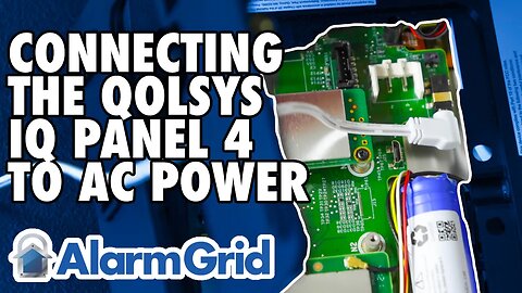
Qolsys IQ Panel 4 - Connecting to AC Power
In this video, Griffin from Alarm Grid shows the viewer how to connect the Qolsys IQ Panel 4 to its transformer for primary power. There are two different ways to attach power to the panel. One is to use the barrel connector on the precut 8' power wire that comes with the panel. The other is to cut your own custom 2-conductor wire and connect it to the terminal block located on the inside of the smart mount bracket as shown in the video.
If you will be using the supplied prepared wire then the connections couldn't be easier. After loosening the set screw at the bottom edge of the panel and pulling the back mounting plate loose, or if the panel is mounted to the wall, pulling the panel loose from the back plate, connect the male barrel connector to the female receptacle located on the back of the IQ Panel 4. Be sure to thread the wire through the hole in the middle of the panel's mounting plate so that it can be properly seated once you're finished.
At the opposite end of the supplied wire, you'll find two pre-connected spade lugs. They are marked Red and Black. Connect the Red spade lug to the screw terminal on the power adapter marked with a positive (+) symbol. Connect the Black spade lug to the screw terminal marked with a negative (-) symbol. Insert each spade lug under the screw, then tighten it down. Once you're finished, put the back mounting plate on the panel and tighten the set screw in the bottom.
If you need a longer wire, then we recommend you use 18AWG stranded 2-conductor wire. With this wire, you can run the IQ Panel 4 power wire up to 98.5' (30m) long. Cut the wire to the length needed without exceeding the 98.5' (30m) limit. It is recommended to use 2-conductor wire with a Black and a Red conductor, to prevent any mixup in the connections. Follow the instructions above to remove the back mounting plate. Locate the terminal block mounted inside this plate. Press down the gray tab opposite each terminal as you make your connections. Connect the Red wire to the spot marked (+). Once the wire is inserted, release the gray tab and press it up, to lock the Red wire in place. Next, connect the black wire to the spot marked (-). Insert the wire into the hole after pressing down on the gray tab. Once the wire is inserted, release the gray tab and press it up to be sure it securely locks the wire into place. Route the wire through the hole in the back of the back mounting plate so that it can be reinstalled securely.
At the other end of the wire, connect the Red lead to the power adapter terminal marked positive (+), and connect the Black lead to the terminal marked negative (-). Once this is done, install the back mounting plate and tighten the set screw on the bottom. You're now ready to plug the panel in. The battery leads should already be connected from the factory. After plugging the panel in, it will likely power up automatically. If it doesn't press the power button on the right side of the panel for about three (3) seconds and the panel should begin to boot up.
https://www.alarmgrid.com/faq/how-do-i-get-ac-power-to-the-qolsys-iq-panel-4
https://www.youtube.com/watch?v=L730w71diJU
62
views
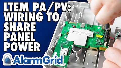
LTEM PA/PV - Wiring to Share Panel Power
In this video, Griffin from Alarm Grid shows the viewer how to wire the LTEM-PA or LTEM-PV so that it gets all its power from the alarm panel. This will prevent the need to use two separate large and bulky transformers. One to power the panel and one to power the communicator. Instead, a single transformer is used to power both. Before you begin, be sure both the panel and the communicator are completely powered down.
If you will be replacing an older GSMX4G or CDMAX, then you should have a wiring harness connecting the existing communicator to the alarm panel. You can use this same harness with the LTEM-P Series communicator. It will plug into the port to the left of the terminal block on the LTEM-PA or LTEM-PV. The harness will only connect to the port in the correct orientation, so no need to worry that you'll connect it wrong. If you don't have a wiring harness, simply make your connections with a 4-conductor piece of wire to the screw terminals.
At the communicator terminal block, connect the Black wire to GND, connect the Red wire to +9V, Connect the Green wire to T (Tx), and connect the Yellow or White wire to R (Rx). If mounting the communicator at the top of the can, thread the wires through the threaded wiring access at the lower left of the communicator. If not, be sure to route the wires through one of the wire access holes so that the cover can attach tightly to the communicator.
Once the wire is properly routed, turn your attention to the connections at the panel. In this video, we show the connections for a VISTA-21iP, which are the same for a VISTA-20P and a VISTA-15P. If you are connecting to a VISTA-128BPT or a VISTA-250BPT, refer to the FAQ associated with this video, linked at the bottom, to verify the proper terminals to use. On the VISTA-21iP and similar panels, connect Black to Terminal 4, Red to Terminal 5, Green to Terminal 6, and Yellow to Terminal 7.
With the connections made, you're ready to power the system back up. Connect the panel's AC power, then its battery. You can choose to connect the communicator's battery as well, but if you do, it will draw slightly more current from the panel. There may be advantages to doing this though, as explained in the FAQ that accompanies this video.
https://www.alarmgrid.com/faq/how-do-i-wire-the-ltem-pa-or-ltem-pv-to-share-panel-power
http://alrm.gd/get-monitored
2
views
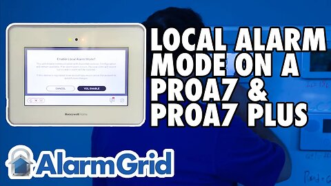
PROA7 or PROA7PLUS: Local Alarm Mode
In this video, John from Alarm Grid explains what Local Alarm Mode is, and how to put a PROA7, PROA7C, PROA7PLUS, or PROA7PLUSC into Local Alarm Mode.
Local Alarm Mode allows an installer or user to work with the ProSeries panel, add zones, test devices, and perform any functions not related to the panel communicating with a monitoring station or Total Connect 2.0. When not in Local Alarm Mode, all ProSeries panels will immediately attempt to connect with the AlarmNet360 servers and then register. If they can't do so, because an account doesn't yet exist on the server, they will show a communication error. They will continue trying to connect and eventually show this error until either the panel is put into Local Alarm Mode, or an account is created and the panel is able to successfully register. If you're a DIYer and you're installing your own panel in preparation for an activation appointment, this is very annoying.
To put the panel into Local Alarm Mode:
Press the Menu Icon, sometimes called the Hamburger Menu
Scroll down to Tools
Enter the Installer Code. The default is 4112
Click on Local Alarm Mode
Toggle the Feature to ON
Click "YES, ENABLE" when prompted.
The panel will reboot, and while doing so, it disables the communicator. This reboot can take several minutes.
When you are finished programming and it's time to activate your ProSeries panel for monitoring, be sure to reverse this process to enable the communicator again.
https://www.alarmgrid.com/faq/what-is-local-alarm-mode-on-a-proa7-or-proa7plus
http://alrm.gd/get-monitored
14
views
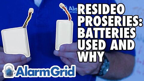
Resideo ProSeries: Batteries Used and Why
In this video, John from Alarm Grid explains why the PROA7 and PROA7PLUS panels seem to have different types of batteries. When the ProSeries panels were engineered, they were made to work with a two-cell approximately 5,000 mAh battery. This battery provides the required standby power in the event of a power failure. The UL requirement is that the battery be able to power the panel for at least 24 hours.
At the time the panels were released, due to COVID-19 and supply chain issues, Resideo (the manufacturer of the ProSeries panels) was unable to source the two-cell batteries. For that reason, they were forced to release them with a three-cell approximately 7,500 mAh battery. Obviously, this battery would also supply the necessary power to support the panel for at least 24 hours during an extended power outage. However, this is not the battery that was intended to be used with the panel, and I'm sure it was also a more expensive option, so once the supply chain issues were resolved and the original two-cell battery was available, Resideo stopped offering the higher-capacity battery option. This is why, if you purchased a panel when they were first made available and you've since purchased a replacement battery, the replacement looks different than your panel's original battery.
https://www.alarmgrid.com/faq/why-did-they-switch-batteries-on-the-resideo-proseries
http://alrm.gd/get-monitored
24
views
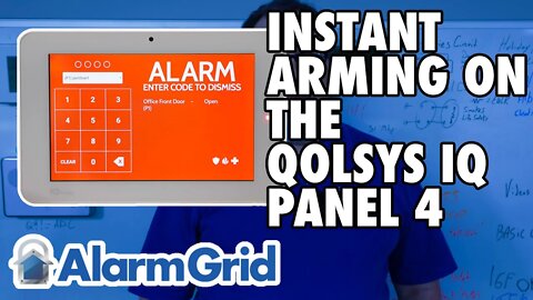
The Qolsys IQ Panel 4: Instant Arming
In this video, John from Alarm Grid shows the user how to arm in Instant Mode from the Qolsys IQ Panel 4. Arming in Instant Mode does not mean that the panel is armed as soon as you press the arming button. Instead, it means that once you press the arming button and the exit delay period has expired, all active zones become instant alarm zones. Basically, it means that the entry delay period has been disabled for this particular armed period.
With the Qolsys IQ Panel 4, you can choose to disable the Entry Delay for either Stay or Away arming. Usually, this is done when arming in the Stay mode at night when a home's occupants are no longer planning to leave or enter the home. If an intruder attempts to enter during the night, they will not be given any entry delay period, but instead, an alarm will be instant. Arming Away with no entry delay is an option when a family is leaving on vacation, for example, and there are no plans for anyone to enter the home while they are away. Of course, this would mean they will need some way to disarm the system themselves once they get back home, prior to entering. Alarm.com remote services are perfect for this. Another option would be to disarm using a key fob while still outside.
To use the Instant option simply press the Disarmed icon from the security screen on the IQ Panel 4. Press the right arrow icon on the arming screen. The full arming screen will then be displayed. In the lower right, click the button that says "Entry Delay ON". This will toggle the option to "Entry Delay OFF". Then choose either Stay or Away arming. The system will still provide a normal Exit Delay (unless you also choose the "Exit Sounder OFF" option, as this will silence the exit sounder, but will also double the amount of exit delay time). Once the system is armed, any active zone will be treated as though it were programmed as a perimeter sensor and will provide an instant alarm when faulted.
https://www.alarmgrid.com/faq/does-the-qolsys-iq-panel-4-support-instant-arming
http://alrm.gd/get-monitored
8
views

2GIG Edge: Entering Programming Mode
In this video, John from Alarm Grid shows you how to enter programming on a 2GIG Edge system. The 2GIG Edge is an all-in-one system with WIFI and cellular communicators built in. It has a Z-Wave Plus V2 controller and a beautiful 7" touchscreen.
To enter programming, press the settings icon, which looks like a gear and is located in the lower right side of the screen. When prompted enter the Installer Code. The default Installer Code is 1561. If you enter the Master Code instead of the Installer Code, you will enter a different menu with different options, but panel programming will not be accessible from this menu.
After entering the Installer Code, you'll be taken to the Installer's Menu. Scroll down to the bottom row. Press the Installer Toolbox icon. This brings you into the menu containing Panel Programming.
Within the Panel Programming Menu, you will see options for Wireless Zones, Built-in Zones, Keyfobs, Keypads, Image Sensors, Network Settings, and Advanced Settings. Go through each menu option until you have configured your panel. ln most cases, settings are saved automatically as you go.
To exit programming, you can press the back arrow at the upper right side of each screen until you completely exit. Alternatively, you can press the House icon in the lower right to return to the main screen.
https://www.alarmgrid.com/faq/how-do-i-get-into-programming-on-my-2gig-edge
http://alrm.gd/get-monitored
7
views
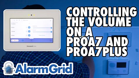
PROA7 and PROA7PLUS: Controlling the Panel Volume
In this video, Darrell from Alarm Grid shows you how to control the volume on a PROA7 or PROA7PLUS alarm panel. The same steps can be used to control the volume on a PROA7C and a PROA7PLUSC.
First of all, only the volume for announcements such as chime sounds and voice chime, arming and disarming announcements, and other status announcements can be controlled. Alarm and trouble sounds use a preset volume that cannot be controlled by the end user.
To change the panel volume, touch the tab at the top center of the panel's touchscreen. A menu will drop down. The volume is controlled by a slider located on the right side of the menu screen. As you slide the volume bar left and right, left to lower the volume, and right to raise it, you will be provided with a sample sound so that you determine the right volume level for you. Once you are satisfied with the volume setting, you can select the X in the upper right side of the screen to close the menu. Settings are automatically saved.
In addition to panel volume, screen brightness can also be edited on this menu screen. It is also adjusted using a left and right slider. Chime and Voice can be toggled on and off, as can Alexa. The status for the system battery, cellular communicator, Bluetooth, AC Power, and WIFI can be seen in the upper left side of the screen. At the lower right you'll see an option for "Clean Screen". Touching this will provide a 30 second countdown window in which you can wipe the screen without performing any touchscreen inputs to the system. At the end of 30 seconds, the system goes back to normal.
https://www.alarmgrid.com/faq/how-do-i-turn-down-the-volume-on-a-proa7-or-proa7plus
http://alrm.gd/get-monitored
3
views

PROA7 or PROA7PLUS: Factory Resetting
In this video Darrell from Alarm Grid shows you how to set a PROA7 or PROA7PLUS, PROA7C, or PROA7PLUSC back to factory default.
Setting a panel back to factory default is a good idea when dealing with a new panel fresh out of the box. You never know what kind of Quality Assurance testing may have been performed on the panel, and a default before programming is a good idea. However, once the panel has been configured, all other troubleshooting steps should be performed before setting the panel back to factory default. A default in haste can cause some issues.
When you set the panel back to factory default, you erase everything except any firmware updates that may have been performed on the panel since it was initially programmed. All zones, Z-Wave devices, user codes and any other programming parameters the panel may have had will be set back to the default values. The Installer Code will go back to 4112, and the Master Code will go back to 1234.
Any SiX or PROSIX devices will be removed from panel programming. It is important to be sure that all SiX or PROSIX sensors that have been programmed to the panel are present and powered up at the time of the panel default. If they are not, then they will not receive the Unpair command that the panel will send out during the default process. Any sensors that do not receive this Unpair command will get stuck in a sort of Limbo, where they won't work with this panel anymore, but also won't allow themselves to be programmed back to this, or to any other, panel.
This is because these encrypted sensors know when they have been paired with a panel, and if they don't receive a signal from that panel releasing them, they will continue to behave as though they are paired. This means they won't even attempt to pair with a new panel. You can tell this is the case if the green LED on the device flashes slowly, instead of fast, when you remove the cover or otherwise transmit with it.
Depending on the timing of the panel default, you may be able to default the sensors themselves, but only if the attempted sensor default occurs within 24 Hours of initial enrollment with the panel. To default most SiX or PROSIX devices, remove the batteries, press and hold the tamper switch, then reinsert the battery while continuing to hold down the tamper switch. If the default is successful, you will see a green LED begin to rapidly flash on the sensor. A SiX or PROSIX sensor that doesn't receive that Unpairing message from a defaulted panel, and can't be defaulted itself, will likely have to be replaced.
Z-Wave devices that were included with the defaulted panel will have to be excluded, then included, either back to the same panel, or to some other Z-Wave controller. If your system is monitored, be sure to put your system on test with the monitoring company prior to performing the system default. Once the default has been completed, a monitored system can likely be reprogrammed with information backed up to the AlarmNet360 server. Contact your dealer for more information.
To perform the default: From the Home screen, press the Menu Icon - Tools - Enter Installer Code (Default = 4112) - Default Options - Factory Default - Confirm you wish to default. The panel should reboot. Be sure that all SiX or PROSIX sensors revert to a fast-blinking green LED.
http://alrm.gd/get-monitored
https://www.alarmgrid.com/documents/defaulting-six-sixa-and-prosix-series-devices-dated-2019
https://www.alarmgrid.com/faq/how-do-i-factory-reset-my-proa7-or-proa7plus-alarm-system
14
views
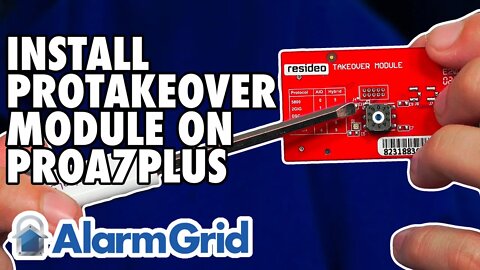
Honeywell Home PROA7PLUS: Installing PROTAKEOVER
In this video, Michael from Alarm Grid shows users how to install the PROTAKEOVER module to a Honeywell Home PROA7PLUS. This same procedure can be used on the Honeywell Home PROA7, Resideo PROA7C, and Resideo PROA7PLUSC panels.
The PROTAKEOVER is a legacy RF receiver module that allows the system to communicate with legacy RF sensors that may already be installed in a monitored location. The legacy RF sensors supported are Honeywell 5800 Series 345 MHz, 2GIG 345 MHz, Qolsys and Interlogix/GE 319.5 MHz, DSC 433 Mhz, or Bosch 433 MHz. The PROTAKEOVER module comes with its own backplate. The original backplate must be replaced with the new one. The new backplate has the antenna built into it, so it MUST be used. There is currently no option to use the PROTAKEOVER with a desk-mounted system.
It is important to set the dial on the PROTAKEOVER prior to inserting it into the panel. Otherwise, the dial is inaccessible once inserted. After removing power from the panel by unplugging the DC Power Adapter, and removing the set screw, pull the panel from the original backplate. Disconnect the backup battery to power the panel completely down. It is important to save the blue terminal block from the original backplate, as you will need it for the PROTAKEOVER backplate. Once the terminal block has been clicked into the proper place, mount the PROTAKEOVER backplate in the location where the original backplate was installed. Reconnect the power wires, if necessary, making sure to observe proper polarity. At this point, the DC Power Adapter should still be unplugged.
Now, turn your attention back to the panel itself. When you turn the panel over, you'll see a plate that slides off to the right. The PROTAKEOVER will mount in the upper-right corner of the panel (when the PROA7PLUS is facing away from you). Double check the dial before inserting it, to be sure it is set for the proper takeover frequency. Slide the PROTAKEOVER into place and install its set screw. Slide the white cover plate back into place. You'll see two (2) metal pins that stick out at the side of the PROTAKEOVER, these will connect to metal connection points on the antenna that is installed inside the replacement backplate.
Reconnect the backup battery. Then, mount the panel to the newly installed PROTAKEOVER backplate, making sure it seats properly. Plug the transformer in, then wait for the PROA7PLUS to boot up. You can now begin to add legacy RF sensors to the PROA7PLUS zones. The panel can support up to 123 legacy RF sensors and up to 127 PROSIX sensors for a total of 250 Zones. As long as the panel firmware is on the latest version, the PROA7PLUS and PROTAKEOVER can even support life-safety 5800 Series Wireless Zones.
https://www.alarmgrid.com/faq/how-do-i-install-a-honeywell-home-protakeover-in-a-proa7plus
http://alrm.gd/get-monitored
9
views

Newest Bloopers
This is a compilation of outtakes from the first video shoot in our Kentucky office. This was the first time any of these technicians stepped in front of the camera to share their vast knowledge regarding security systems and equipment. They were understandably a tad bit nervous!
We started Alarm Grid with the idea that most folks can install and configure their own alarm system, and that doing so can save a lot of money. To that end, we share our knowledge of alarm systems freely in both written and video form. The technicians at Alarm Grid have nearly a century of combined alarm experience, with many of those technicians having other electronic system experience prior to their entry into the alarm industry.
We find that users who set up and configure their own alarm system are more likely to use their system, and less likely to have false alarm issues due to user error. Installing and configuring your own system gives you a level of comfort with using the system that you just don't get when it's installed and configured by someone else. Even if they go through the process of training you properly on its use once the installation is complete. But, in many cases, that training never happens.
So, that's why we produce so much written content, and why we make these videos, to empower our customers, and future customers, to take control of their own security.
Now, enjoy a few laughs at our expense.
http://alrm.gd/get-monitored
11
views
PROA7 or PROA7PLUS: Entering Programming
In this video, Darrell from Alarm Grid shows users how to enter programming mode on a Honeywell Home PROA7 or PROA7PLUS, or on a Resideo PROA7C or PROA7PLUSC.
To enter programming, tap the menu icon in the bottom center of the screen. Scroll down to Tools, then enter the current Installer Code. The default Installer Code is 4112. This will bring you into the Installer Tools menu.
From here, select Programming from the available options. Once you enter programming, you can edit the number of partitions, add/edit/delete any peripheral devices, including Sensors, Key fobs, or keypads. In Z-Wave Peripherals, you can Include or Exclude devices. In the Users' programming, you can add/edit/delete user codes. In Panic Alarms, you can configure the keypad panic options, and in Advanced Settings, communicator and other system settings are configured.
In addition to system programming, the Installer Tools Menu can allow you to view System Information, Perform System Tests on both communicators and Sensors, Enable or Disable Local Alarm Mode, Change the Installer PIN, Default the panel back to factory settings, and Reboot the panel.
To exit programming when you're finished, choose the left arrow in the upper-left side of the screen to go back to the previous screen. Keep doing this until you return to the main Security Screen.
https://www.alarmgrid.com/faq/how-do-i-get-into-programming-on-my-proa7-or-proa7plus
http://alrm.gd/get-monitored
3
views
2GIG Edge: Setting Date/Time
In this video, Griffin from Alarm Grid shows you how to manually set the date and time on a 2GIG Edge via the panel. It is important to note that any system that is monitored through Alarm.com will have the local settings overridden by the information from Alarm.com. This is why it is important for monitored panels to have the proper time zone set.
To set the date and time via the panel, for those panels that aren't being monitored, access the menu by clicking the gear icon in the bottom-right of the panel's main screen. Enter the Installer Code, the default is 1561. Then click the option for Date & Time.
Once in the Date & Time Menu, you have sliders for the Hour, Minute, and AM/PM. You then have sliders for Month, Day, and Year. Once the proper settings have been made, click the green SET button at the bottom right. You can now press the Home Icon in the lower right corner of the screen.
To set the proper time zone via the website or the customer app, the steps are basically the same. Log into the account either via the app or by going to www.alarm.com/login. Go to Settings when using the webpage, click the hamburger menu icon in the upper-left when using the app. Now, via either method, scroll down to Account Management, then System Information, then at the bottom of the page/screen, you'll see the time zone setting. From the drop-down menu, select the proper time zone, then press the Update button to save your changes. It may take a few minutes for your programming change to be reflected at the panel.
https://www.alarmgrid.com/faq/how-do-i-change-the-date-time-on-a-2gig-edge
http://alrm.gd/get-monitored
4
views
Honeywell Home PROSIXFOB: Adding to a PROA7 or PROA7PLUS
In this video, Darrell from Alarm Grid explains how to enroll a PROSIXFOB with a PROA7 or PROA7PLUS alarm panel. This same procedure will also work on the Resideo PROA7PLUSC and PROA7C.
First, enter panel programming by selecting the hamburger Menu icon at the bottom-center of the panel screen. Scroll down to Tools, then enter the Installer Code. The default is 4112. Choose Programming, then Peripherals. Press the + icon in the upper-right of the screen. This puts the panel into Learn Mode.
Simultaneously, press the top two buttons on the PROSIXFOB or SIXFOB. The two green LEDs should begin to flash rapidly back and forth. If this does not happen, it means that the PROSIXFOB or SIXFOB has already been paired with a panel. In order to use it, it will need to first be unpaired or defaulted. The PROSIXFOB and SIXFOB can only be defaulted within the first 100 transmissions after being paired with a system.
https://www.alarmgrid.com/documents/defaulting-six-sixa-and-prosix-series-devices-dated-2019
Since this is an encrypted device, the pairing process can take a little time, so be patient. Once the panel has been paired with the fob, the information for default fob programming can be seen, along with the first zone number assigned to the fob, and the MAC address. Verify that the MAC address you are dealing with matches the MAC address for the fob.
One important programming step is assigning the key fob to a user code. By default, there is a Master code programmed for the panel, and by default, the fob will be assigned to the Master code. You can assign each fob to a unique user so that when the fob is used, the event log will show that the user armed or disarmed the system. In order to assign a fob to a user, you must program the user code BEFORE you program the fob. Otherwise, that user will not be available to choose from the drop-down when programming the key fob.
By default, "4-button" fob is the device type selected and is the programming shown in this video. A SIXFOB or PROSIXFOB can use up to eight (8) different functions using both single-button presses, and combination button presses. The default programming for the bottom-right button (the red exclamation mark) is "No Response". If you would like to use this button as a panic, you can change the programming accordingly. The other three buttons are programmed for Disarm (upper-right), Away (upper-left) and Stay (lower-left). After all the programming is completed, be sure to press "Save". You can then exit programming and test the PROSIXFOB or SIXFOB to be sure it's working properly.
https://www.alarmgrid.com/admin/questions/how-do-i-add-a-prosixfob-to-a-proa7-or-proa7plus-panel/edit
http://alrm.gd/get-monitored
6
views
LTEM PA/PV: Installation with a Vista 20P
In this video, Griffin from Alarm Grid shows you how to connect a Resideo LTEM-PV (or LTEM-PA) to a VISTA-20P panel when the communicator is using its own power adapter. When any of the add-on modules are used, such as the PROWIFIZW, PRODCM Dialer Capture Module, or a separate LTE module, then the LTEM-PV or LTEM-PA should be connected to its own power adapter and should have its own battery.
Start by making sure all equipment is powered down. This includes both battery and primary power for both the VISTA-20P and the LTEM-PV or LTEM-PA. Be sure the transformer and battery for the panel are both unplugged, and that the DC Power Adapter and battery for the communicator are also disconnected.
One thing we don't touch on in this video, that is important, is the routing of wire. You want to be sure that any wires that will traverse to the outside of the LTEM-PV or LTEM-PA are routed in such a way that the cover can be securely attached once your work is complete. This means either routing the wire through the provided hole at the bottom of the communicator, as shown by Griffin in the video, routing it through the back of the communicator and fishing the wire through the wall, or using one of the plastic knock-outs in the side of the backplate to route the wires so that the cover can be properly seated.
Whether you use an LT-Cable, as suggested in the video, or just a pair of wires you have laying around, be sure to observe proper polarity between the DC Power Adapter and the LTEM-PV or LTEM-PA. Connect the Black wire to the terminal marked Negative (-) on the power adapter, and connect the Red wire to the terminal marked Positive (+). At the Communicator end, connect the Black wire to (GND), and connect the Red wire to (+9VDC).
The LTEM-PV and LTEM-PA come with a wiring harness to allow for an easy connection between the communicator and the alarm panel. The plastic header is keyed, so you can't plug it in the wrong way. This harness offers a precut length of wire. In some cases, this won't be long enough, and you'll either have to splice your own wire into the harness wire ends, or you'll have to use the terminals on the communicator, instead of the harness, and cut your own wire. If you do need to use your own wire, be sure to make the proper connections at both ends, the communicator and the alarm panel. The FAQ linked at the bottom of this description shows you both ways of wiring, in detail.
Connect the harness to the port on the communicator, route the wires properly so that the cover can be securely fastened to the communicator when you're finished, and make your connections at the panel. The Black wire from the harness connects to Panel Terminal 4, the Yellow wire from the harness connects to Panel Terminal 7, and the Green wire from the harness connects to Panel Terminal 6.
Once all wires are connected, start by connecting the battery to the LTEM-PV or LTEM-PA, then plugging in the DC Power Adapter. Connect the transformer for the VISTA-20P first, then connect the backup battery. Be sure that both the panel and the communicator complete the power-up sequence and then perform any programming necessary to complete the LTEM-PV or LTEM-PA configuration.
https://www.alarmgrid.com/faq/how-do-i-install-a-resideo-ltem-pa-or-ltem-pv-to-a-honeywell-vis
http://alrm.gd/get-monitored.
23
views
2GIG Edge: Upgrading the Firmware
In this video, John from Alarm Grid explains the two (2) ways that a 2GIG Edge can be updated. The easiest way is an Over-the-Air (OTA) update. This option is available when the panel is being monitored through Alarm.com. The Firmware can be pushed out to the panel via WIFI, which is a free update, or if WIFI is not available at the panel, the update can be pushed via Cellular. For Cellular OTA updates, a fee will be applied, depending on the size of the update file. Alarm Grid passes this fee on to our customers with no markup.
If you prefer, you can download the firmware files from the Alarm Grid site and can then apply the update to the panel using the USB port located on the top of the system. The link to Alarm Grid's 2GIG Edge firmware update page is available below. Once you download the firmware files, and get them onto a USB stick. The USB drive should have a capacity between 1GB and 16GB, and should be formatted using FAT32. Also, be sure the USB Drive has only one (1) partition and when you save the files to the USB drive, be sure they are saved in the root directory. The file you download should have a format similar to: genesis-meta-A.3.1.0.011-image-xe.2gig. Do not change the file extension.
Once the proper update file is on the USB drive, place the drive into the port on the top of the panel. The system will check the drive, and if it contains an update, a message will pop up asking if you would like to update the panel. You will be required to enter either the Installer or Master Code (1561 or 1111 respectively, by default). The update will begin. The panel may reboot more than once during this process, and when it is finished, a message on the panel will tell you so. You can then remove the USB Drive, and replace the rubber protector over the panel's USB port.
If the USB drive does not contain a newer version of firmware, meaning the panel is already on the version contained on the drive, or newer, then the panel will not prompt you to update based on what's contained on the USB drive. You can simply remove it.
https://www.alarmgrid.com/faq/how-do-i-upgrade-my-2gig-edge-panel-s-firmware
https://www.alarmgrid.com/downloads/2gig-edge-firmware-updates
http://alrm.gd/get-monitored.
18
views