
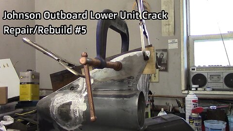
Johnson Outboard Lower Unit Crack Repair/Rebuild #5
Video #5 of the Johnson GT 150 lower unit crack repair/rebuild is on straightening and repairing the skeg.
First clean up the area of the skeg you want to weld repair, assess the skeg straightness, and how you want to go about straightening it, every situation is a little different. Check the skeg with a straight edge to see exactly where it is bent. This skeg has a bow in the middle. I have a piece of ¼” x 3” x 3” steel angle, with a section of wood on each side c-clamped to the skeg on each end which leaves a void in the center, so now putting a c-clamp in the center allows me to pull the center straight. Things to remember: this is cast aluminum it will break! Do put too much stress on the c-clamp while straightening, a little at a time while adding heat, aluminum melts at 1221 degrees F, move the heat around as to not heat any one specific area too much. Heating the area you want to straighten and “slowly” adding pressure with the c-clamp is the key to success. You can also do this with the drive still attached as long as it is at its full level of grease. You can also do this with the drive still attached as long as it is at its full level of grease. The grease will dissipate the heat so you don't ruin the seals & O-rings. Notice how my torch is at least 2” away from the section to be heated, and I do not concentrate heat for long in any single area. You could use a temp stick, or a pyrometer to verify you never get close to the 1221 degree melting point. You will need to take it a little beyond straight to get it to stay there after you release the C-clamp, and this is trial and error. But don’t go too far or you’ll get to start over again going the opposite direction, or worse you could break the skeg. Have patience just a little at a time, it may be a slow process but that is what it takes. Always look down the skeg from the end to see/verify your progress. I realize this may be long and boring but I felt you need to see the whole thing. This also created a terrific preheat for the skeg weld repair. I am building up the low areas of the skeg so I can grind the edge straight. I am using 1/16” 5356 aluminum filler wire. I am still not happy with straightness so I will go back again. Now remove the clamp and verify straightness, if it is not yet there you will have to continue, I am satisfied! Ever since I was a kid when I concentrate my damn tongue is hanging out, some day I’ll bite it off! I am now feathering/melting the back side of the weld in with the skeg. Now I can grind off the excess weld and see if I need to add more weld anywhere. I am using a 60 grit sanding disc, and will take it down to a medium cloth disk to remove any deep scratches. Please come back for video 6 grinding the inside of the case, and preparing for reassembly.
https://www.youtube.com/@HRIservicesllcSturgeonBay
https://www.instagram.com/hri_services/
https://www.facebook.com/HRIServicesllc/
https://www.millerwelds.com/
35
views
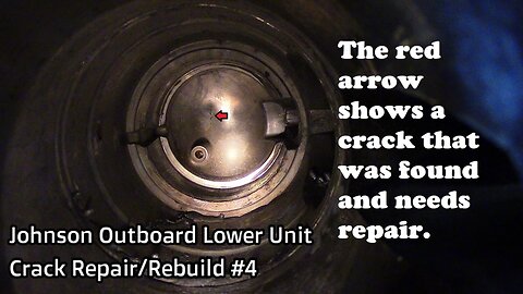
Johnson Outboard Lower Unit Crack Repair/Rebuild #4
Video #4 of the Johnson GT 150 lower unit crack repair/rebuild is on the weld repair of a crack found in the nose of the lower unit where I believe the water seeped into the case which caused the cracking of the case in winter storage. What you will see being completed in this series of videos will be questionable to many. This is the second lower unit I have repaired in this same fashion, and both went on for many more years of service and saved the owners in the $1000.00 range. If you attempt this I cannot stress enough do not force anything, take your time. Please check video #1 for more of a description.
Link to some tools, including the pinion nut adapter kit:
http://www.sterndrive.info/outboardmotor/id2.html
Link to exploded view of the lower unit: http://www.sterndrive.info/outboardmotor/1978_1998_v4_90_degree_.html
Buy snap ring pliers: https://www.offshoremarineparts.com/93-13-1045.html?gclid=Cj0KCQiA5aTUBRC2ARIsAPoPJk9wFPQBsX-Hotb4B7Ysnl0JFJ8QXMiLgohL8303qvf6221euzjL2qIaAnfrEALw_wcB
At the end of this video I will include a picture of the OMC lower unit diagram that is what the numbers in the video refer to. There will also be a link in the video description to that diagram.
During my inspection of the lower unit I found this crack which is probably where the water got into the case, he probably hit a rock with the lower unit and cracked it but didn’t know.
This is why it is imperative you check the grease for water each year in the fall prior to storage.
Time to make some noise, I beveled out the crack in the nose and need to weld repair that first.
Cast aluminum welding is a time consuming process that is why I am showing this whole section uncut.
I use 100% argon for a shielding gas.
The crack will open while welding it’s easy to see it you must weld it from end to end with penetration so you can sand it smooth.
There are always some small pin holes that need to be gone over after grinding, that’s cast aluminum.
You can see I am not adding filler wire at this time, I am boiling/burning out the contaminants in the base material.
The porosity just keeps coming back you just have to relax and continue until it boils away.
If the contaminants will not boil out you will need to grind them out.
Now to clean up some of the skeg, and complete a little build up there, come back for video #5 to see me repair and straighten the skeg, and grind the inside of the case. Thanks for watching.
https://www.youtube.com/@HRIservicesllcSturgeonBay
https://www.instagram.com/hri_services/
https://www.facebook.com/HRIServicesllc/
https://www.millerwelds.com/
5
views
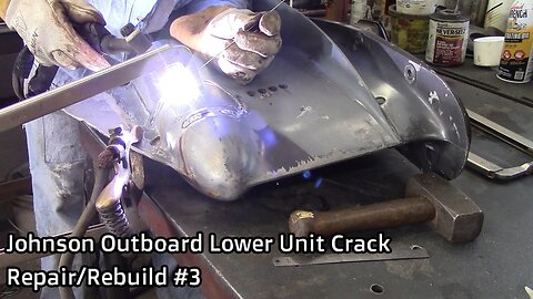
Johnson Outboard Lower Unit Crack Repair/Rebuild #3
Video #3 of the Johnson GT 150 lower unit crack repair/rebuild is on housing clean up, beveling out the crack, and completing the weld repair. This is the second lower unit I have repaired in this same fashion, and both went on for many more years of service and saved the owners in the $1000.00 range. If you attempt this I cannot stress enough do not force anything, take your time. Please check video #1 for more of a description. The music in the sped up sections is called Skinny Leonard by Audionautix is licensed under a Creative Commons Attribution license (https://creativecommons.org/licenses/by/4.0/)
Artist: http://audionautix.com/
Link to some tools, including the pinion nut adapter kit:
http://www.sterndrive.info/outboardmotor/id2.html
Link to exploded view of the lower unit: http://www.sterndrive.info/outboardmotor/1978_1998_v4_90_degree_.html
Buy snap ring pliers: https://www.offshoremarineparts.com/93-13-1045.html?gclid=Cj0KCQiA5aTUBRC2ARIsAPoPJk9wFPQBsX-Hotb4B7Ysnl0JFJ8QXMiLgohL8303qvf6221euzjL2qIaAnfrEALw_wcB
We are going to repair this case!
First to weld aluminum we need to remove all contaminants, oil, grease, water, paint, get it as clean as possible with carburetor cleaner first.
Now we need to grind out a bevel in the case with an angle grinder and a .045” cutting wheel where the crack is so we can get a full penetration weld. I am going to speed this part up.
In this sped up section I will bevel it, remove the paint with a wire wheel, press the broken section back into place and tack weld. You will need to pay attention inside the case, the section that has been machined needs to be virtually perfect when complete that is where the O-ring seals the water section from the gear case grease section.
You want to bevel the crack out and weld beyond the end of the crack to verify there will be no leaks.
I am now welding out the case, notice how I weld a small section at a time alternating areas so I do not put too much stress in any one area of the case, I weld between 1/2” and 1” at a time.
Lower units are cast, made of low grade aluminum and somewhat porous over the years they absorb grease and dirt, and as I beveled it I added extra contaminants, they all have to be boiled out of the weld puddle with aluminum.
I wire brush and sometimes need to grind off the contaminants that boiled to the surface of the weld puddle.
Listen close and you will hear a few oh *hit moments! Then I need to cover a swear word.
Slowly I am becoming aware of what is happening, and am unsure what to do at the moment, here comes a big one.
Now is that time to stop, think, and after you have an idea what’s happening move forward. Some type of internal stress is causing the weld to crack.
The weld is cracking at the nose of the case, I grind out the weld, and my first course of action is to try a preheat.
After a thorough preheat of the case in the welding zone, I go back to welding.
Here it goes again, loud enough it startles me!
Next course of action is to figure out where the stress is coming from and remove it. So I cut across the bottom of the broken section figuring that is where the stress is coming from and bevel that out. Not happy as this means I have to weld across the O-ring sealing section twice. GREAT!
I now try to weld a section at a time and inspect it as I go, and listen for cracking.
I welded out the front side first, then the top, then the back, and well you’ll hear it!
At least it keeps cracking in the same spot. The front section which runs parallel to the O-ring sealing surface and not across it, this is good so I do not booger that up it needs to be welded inside and polished out. Grind the crack out again.
Well that still didn’t work, and it startled me again. What’s the definition of insanity?
There is really only one course of action left.
Turn that #@$%& air compressor off!
Cut the skeg, it is a very thick strong section of the lower unit. It is the only place left that I figured the internal stress could be coming from.
Speed up one more time, after many hours of welding and grinding, I finally removed the stress and got the exterior welded without any cracking. I welded the case complete first, and then the skeg.
Here is the weld completed prior to cleaning up, opposite side of the skeg also. Come back for video #4 when I will weld across the O-ring sealing surfaces inside the case? Please Follow my channels.
https://www.youtube.com/@HRIservicesllcSturgeonBay
https://www.instagram.com/hri_services/
https://www.facebook.com/HRIServicesllc/
https://www.millerwelds.com/
66
views
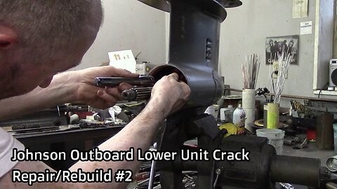
Johnson Outboard Lower Unit Crack Repair/Rebuild #2
Video #2 of the Johnson GT 150 lower unit crack repair/rebuild is on the full disassembly of the lower unit. What you will see being completed in this series of videos will be questionable to many. This is the second lower unit I have repaired in this same fashion, and both went on for many more years of service and saved the owners in the $1000.00 range. If you attempt this I cannot stress enough do not force anything, take your time. Please check video #1 for more of a description.
Link to some tools, including the pinion nut adapter kit:
http://www.sterndrive.info/outboardmotor/id2.html
Link to exploded view of the lower unit: http://www.sterndrive.info/outboardmotor/1978_1998_v4_90_degree_.html
Buy snap ring pliers: https://www.offshoremarineparts.com/93-13-1045.html?gclid=Cj0KCQiA5aTUBRC2ARIsAPoPJk9wFPQBsX-Hotb4B7Ysnl0JFJ8QXMiLgohL8303qvf6221euzjL2qIaAnfrEALw_wcB
At the end of this video I will include a picture of the OMC lower unit diagram that is what the numbers in the video refer to. There will also be a link in the video description to that diagram.
Remove the four bolts #50 (3/8”), holding in the bearing housing seal assembly #76 and remove the assembly.
Sorry for all the air compressor noise in the background.
See the red arrow those are two big snap rings #68 holding the reverse gear #27 in place; they are back to back and miserable to get out. You can buy the correct snap ring pliers for this, (link in this video description) it’s expensive but worth the lost time. I will show you an alternative I found in another video that works.
This is a cheap pair of long straight needle nosed pliers Grind the tips of the nose close to the end to fit and hold in the snap rings. Don’t make them too thin or the tips will break off.
I had the splined driveshaft adapter for removal/installation of the pinion nut from the last lower unit project I did.
I made this pinion nut wrench, I would recommend you buy the factory pinion nut adapter kit, (link in this video description).
You need to get the pinion nut adapter on the pinion nut, the splined driveshaft adapter on the top of the driveshaft and loosen the pinion nut #28 (7/8”), by rotating the driveshaft counterclockwise.
Now we need to go to the top and remove the upper parts of the lower unit so we can lift and turn the driveshaft #21 and thread off the pinion nut to remove the driveshaft.
I am now removing the water pump bolts, #5 (7/16).
Remove the O-ring #80, water pump housing #6, O-ring #7, and water pump plate.
Remove the four bolts #15 (7/16”) from the bearing/seal housing.
Carefully remove the bearing seal housing lift 180 degrees apart. There are 18 loose needle bearings not listed they are part of #16 bearing/seal housing don’t lose any.
I am tapping the shaft in an area where there is no bearing or seal race to ease removal.
Next you will need to remove the shift rod assembly. Loosen and remove bolts #53 (7/16”), and slide cover #66 up.
Push the shift rod down to make sure the unit is in reverse.
The shift rod threads in to #29 detent arm.
Now you can remove the rest of the gear assembly.
The case is fully disassembled so at this point you will want to clean all the gasket surfaces and inspect all parts to see what you need to order and replace. See you in video #3 where I will repair the housing.
https://www.youtube.com/@HRIservicesllcSturgeonBay
https://www.instagram.com/hri_services/
https://www.facebook.com/HRIServicesllc/
https://www.millerwelds.com/
123
views
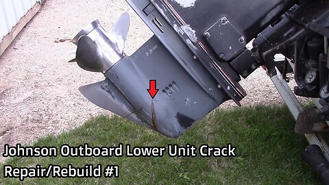
Johnson Outboard Lower Unit Crack Repair/Rebuild #1
This boat was in winter storage in a Wisconsin garage and the oil was never checked for water prior to winter setting in. The result was a cracked lower unit case the water that was in the lower unit froze and broke the case. Depending on where the break is in the case will determine to what extent, and if the case can be repaired. This repair does not run through the oil/water sealing area but is very close, though it does run into the snap ring area, I will not have to weld inside the case on this unit, but I will carefully polish the sealing area for the new o-ring to seal, this repair was very doable. You just have to take your time be careful, and think about what you’re doing before doing it, if it doesn’t feel right stop and think it through. Bottom line is a new lower unit case is not cheap, some models are no longer available, and I know a few people who have bought rebuilt aftermarket lower units and have had many problems with them. I cover all the steps without any sped up sections so the videos may seem long but everything is covered. I completed this work in the spring of 2016. Video #1 of the Johnson GT 150 lower unit crack repair/rebuild is on identification of the needed repair, removing the shift rod bolt, draining the lower unit, and removal of the lower unit. Some of what you will see done in this series of videos will be questionable to many, this is the second lower unit I have repaired in this same fashion, and both went on for many more years of service, and saved the owners in the $1000.00 range, if you attempt this I cannot stress enough do not force anything, take your time. You will need to buy the parts for the rebuild, all seals gaskets water pump etc will need to be replaced so you will have to locate and identify the model and serial numbers of your specific outboard. After you have that information you will need to search the best parts outlet (if you can buy the original manufacturer part)/tutorial videos, and exploded view diagrams, the link below is a good website for information and tooling as you will also have to purchase some tools to complete the task. http://www.sterndrive.info/outboardmotor/index.html
Read the description of this video it will give you some useful information and a link to look at some exploded views, parts, and tools you will need for this project.
The trickiest part about removing the lower unit is removing this bolt that holds the shift rod it is inside the engine cover.
These are the tools you will need to remove/re-install the bolt.
The red arrow is where you need to look to locate the bolt.
This red arrow is the bolt you are looking for.
I do not show the actual process of bolt removal, you would not see in there as I could not fit the camera, tools, and my head all in the same space.
Leave one of the four lower unit attaching bolts in about four turns so when the rest of the bolts are removed the lower unit does not drop.
I am taking the last bolt out now while holding the lower unit in place. I hit a tight section of the bolt and need a wrench, be right back.
That’s it the lower unit is removed see you in video #2. Please like and subscribe.
Great information including videos and exploded views of many different OMC models: http://www.sterndrive.info/outboardmotor/index.html
https://www.youtube.com/@HRIservicesllcSturgeonBay
https://www.instagram.com/hri_services/
https://www.facebook.com/HRIServicesllc/
https://www.millerwelds.com/
612
views
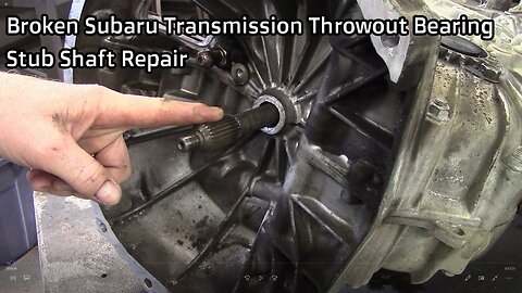
Broken Subaru Transmission Throwout Bearing Stub Shaft Repair
On a Subaru manual transmission the throwout bearing stub that the throwout bearing slides on is made of aluminum and is an integral part of the two transmission halves, after the grease wears off the throwout bearing starts to stick and eventually breaks off these parts. I stand the transmission on end add water to the webbing of the transmission to keep the seal which is ¾” below the webbing cool, tack weld the two halves together on the end to give it a little more strength and weld it back in place leaving the separation line unwelded in case the two halves would ever need to be split for repair.
https://www.subaru.com/index.html
https://www.youtube.com/@HRIservicesllcSturgeonBay
https://www.instagram.com/hri_services/
https://www.facebook.com/HRIServicesllc/
https://www.millerwelds.com/
6
views
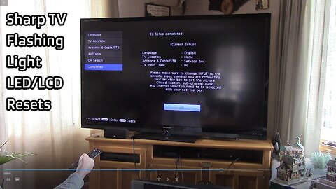
Sharp TV Flashing Light LED/LCD Reset
So one morning I turned my Sharp Aquos 70” LC-70LE734U TV off and then right back on again and it would not come back on it had a fast flash and a slow flash on the light. I searched this on YouTube and found a video by Tampatec, to reset your TV but it seems he missed one step, after reading many forum posts, and watching a lot of YouTube videos, going to Shop Jimmy, etc. I was pretty much convinced I was going to have to strip my set down and look for bad LED lamps. Then I found a string on “Toms Guide” forum that someone ran into by accident just trying different variations of the button sequence. If you just plug your set back in after the reset it will just go back into the same cycle of one fast flash one slow flash. But if you hold down the power button until the TV comes on while plugging it back in it will reset. So I will run through the whole sequence.
Unplug the TV, press and hold volume down button and the input button on TV while plugging in the TV until it comes on. Then press Volume down button and channel down button at the same time and the TV will open up the service menu. Use channel and volume buttons either on the remote or on the TV to move through and toggle on off on the service menu. Channel up & down moves and highlights different sections in the menu, and the volume up & volume down toggles a selection on or off. On page 2 start at “Lamp Error Reset” toggle it to on, then up to “Reset” toggle that one to on, then up to “Industry INIT” toggle it to on and click the OK/enter button on the remote. The green screen will come up indicating the reset was good. Then unplug the TV again, push and hold the power button on the TV while plugging the TV back in, as the TV come on it will go directly to the TV set up page.
*There still may be some internal issue with the TV because every time the set loses power it will revert back into the same fast flash, slow flash sequence, and you will have to do it all again, as long as the set is not unplugged or does not lose power it will continue to work as it should.
Video from Tampatec: https://www.youtube.com/watch?v=ZG7us0urbDo&t=143s
Forum string from Toms Guide: http://www.tomsguide.com/forum/58779-4-sharp-power-button-flashing
https://www.youtube.com/@HRIservicesllcSturgeonBay
https://www.instagram.com/hri_services/
https://www.facebook.com/HRIServicesllc/
76
views
Welding Pop Cans
I made this video as a request from Richard Kicklighter, he requested I weld very thin sheet aluminum, and explain the settings, cup, tungsten, gas, etc. I didn't have any thin aluminum sheet stock so I thought I've always wanted to try welding two pop cans together so that's what I did.
https://www.youtube.com/@HRIservicesllcSturgeonBay
https://www.instagram.com/hri_services/
https://www.facebook.com/HRIServicesllc/
https://www.millerwelds.com/
22
views
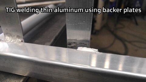
TIG welding thin aluminum
This video is on TIG (Tungsten Inert Gas) welding thin aluminum, but it is also pertinent to other thin materials. Bad factory welds due to the thin material and no heat sink used when the factory built it lead to the failure of many welds on this cart. I will run through some of the basics for welding thin aluminum and the use of a heat sink or backer plate.
https://www.youtube.com/@HRIservicesllcSturgeonBay
https://www.instagram.com/hri_services/
https://www.facebook.com/HRIServicesllc/
https://www.millerwelds.com/
69
views