Johnson Outboard Lower Unit Crack Repair/Rebuild #2
Video #2 of the Johnson GT 150 lower unit crack repair/rebuild is on the full disassembly of the lower unit. What you will see being completed in this series of videos will be questionable to many. This is the second lower unit I have repaired in this same fashion, and both went on for many more years of service and saved the owners in the $1000.00 range. If you attempt this I cannot stress enough do not force anything, take your time. Please check video #1 for more of a description.
Link to some tools, including the pinion nut adapter kit:
http://www.sterndrive.info/outboardmotor/id2.html
Link to exploded view of the lower unit: http://www.sterndrive.info/outboardmotor/1978_1998_v4_90_degree_.html
Buy snap ring pliers: https://www.offshoremarineparts.com/93-13-1045.html?gclid=Cj0KCQiA5aTUBRC2ARIsAPoPJk9wFPQBsX-Hotb4B7Ysnl0JFJ8QXMiLgohL8303qvf6221euzjL2qIaAnfrEALw_wcB
At the end of this video I will include a picture of the OMC lower unit diagram that is what the numbers in the video refer to. There will also be a link in the video description to that diagram.
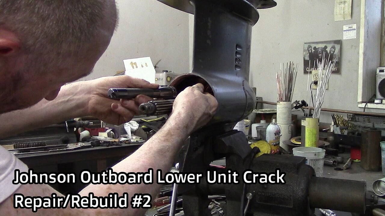
Remove the four bolts #50 (3/8”), holding in the bearing housing seal assembly #76 and remove the assembly.
Sorry for all the air compressor noise in the background.
See the red arrow those are two big snap rings #68 holding the reverse gear #27 in place; they are back to back and miserable to get out. You can buy the correct snap ring pliers for this, (link in this video description) it’s expensive but worth the lost time. I will show you an alternative I found in another video that works.
This is a cheap pair of long straight needle nosed pliers Grind the tips of the nose close to the end to fit and hold in the snap rings. Don’t make them too thin or the tips will break off.
I had the splined driveshaft adapter for removal/installation of the pinion nut from the last lower unit project I did.
I made this pinion nut wrench, I would recommend you buy the factory pinion nut adapter kit, (link in this video description).
You need to get the pinion nut adapter on the pinion nut, the splined driveshaft adapter on the top of the driveshaft and loosen the pinion nut #28 (7/8”), by rotating the driveshaft counterclockwise.
Now we need to go to the top and remove the upper parts of the lower unit so we can lift and turn the driveshaft #21 and thread off the pinion nut to remove the driveshaft.
I am now removing the water pump bolts, #5 (7/16).
Remove the O-ring #80, water pump housing #6, O-ring #7, and water pump plate.
Remove the four bolts #15 (7/16”) from the bearing/seal housing.
Carefully remove the bearing seal housing lift 180 degrees apart. There are 18 loose needle bearings not listed they are part of #16 bearing/seal housing don’t lose any.
I am tapping the shaft in an area where there is no bearing or seal race to ease removal.
Next you will need to remove the shift rod assembly. Loosen and remove bolts #53 (7/16”), and slide cover #66 up.
Push the shift rod down to make sure the unit is in reverse.
The shift rod threads in to #29 detent arm.
Now you can remove the rest of the gear assembly.
The case is fully disassembled so at this point you will want to clean all the gasket surfaces and inspect all parts to see what you need to order and replace. See you in video #3 where I will repair the housing.
https://www.youtube.com/@HRIservicesllcSturgeonBay
https://www.instagram.com/hri_services/
https://www.facebook.com/HRIServicesllc/
https://www.millerwelds.com/
-
 1:28:54
Adam Does Movies
14 hours ago $0.12 earnedTalking Movie News + AMA - LIVE!
24K2 -
 2:34:47
SquallRush
15 hours agoDragon Ball Tuesday! + Reverse Nuzlocke with @DTDUBtv
34.7K3 -
 1:45:49
megimu32
4 hours agoON THE SUBJECT: Can I Get a Remix? Diddy, Gaga & Headlines That Sound Fake
34.4K5 -
 19:07
19:07
Stephen Gardner
4 hours ago🚨Steve Bannon Predicts Chaos and a Constitutional Crisis!
49.3K48 -
 1:07:06
Anthony Rogers
8 hours agoEpisode 365
22.9K1 -
 LIVE
LIVE
SpartakusLIVE
6 hours agoVerdansk SOLOS || #1 WZ MACHINE
171 watching -
 3:52:22
Geeks + Gamers
6 hours agoTuesday Night's Main Event
46.2K1 -
 LIVE
LIVE
Spartan (Pro Halo esports Player)
9 hours agoPro Halo Player | Back to Streaming | Warming up then scrims no comms | !optimization #ForTrav !ads !loginfix
81 watching -
 38:11
38:11
Anthony Pompliano
7 hours ago $3.05 earnedWhy Isn’t Bitcoin $150K If Everyone’s Buying?
78.1K12 -
 58:07
58:07
BonginoReport
7 hours agoCollege Campuses are Cesspools of Violence, Hatred and Division - w/ Hayley Caronia (Ep.42)
134K88