
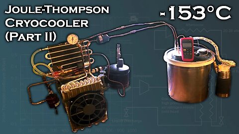
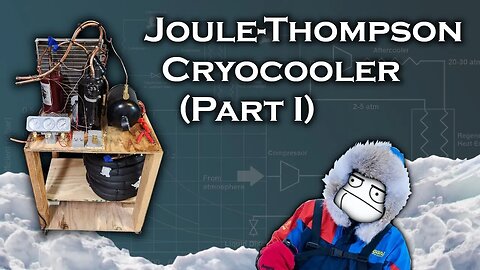
Joule-Thomson Cryocooler Part II (-153°C)
100923 In this video, I'll build on my progress from the last Joule-Thomson
cryocooler video and reach a temperature of -153C on a single stage
using parts sourced from window A/C units and common/cheap substances as
refrigerants (a mixture of Propane, Ethylene, and Methane). This
temperature is low enough to condense any gas except for Hydrogen,
Helium, or Neon, at the following pressures:
Nitrogen - 25.3 barA (352 PsiG)
Air - 20.2 barA (278 PsiG)
Oxygen - 10.3 barA (135 PsiG)
Methane - 1.9 barA (13 PsiG)
I tested several different mixtures to achieve this temperature, but the
best performing I've found so far has been a 30/20/50 blend of Propane,
Ethylene, and Methane, respectively. The Propane comes from an ordinary
grilling tank, the Ethylene is produced by heating denatured alcohol
over a catalyst, and the Methane comes from residential natural gas. All
these sources are very cheap.
For a throttling valve to achieve the Joule-Thomson effect, I use a 1m
long 1mm ID capillary inline with a computer-controllable electronic
expansion valve (EEV) used for fine-tuning flow resistance. I avoid
using *only* an EEV due to the relatively large thermal conduction
losses experienced through the bulky metal valve body.
The system is charged with 180 PsiG (11.3 BarA). With the EEV wide open,
the high/low side pressure is ~400/65 psiG (28.6/5.5 barA) respectively.
With the EEV closed as far as possible without shutting off the flow,
the high/low side pressure is ~520/10 psiG (36.9/1.7 barA) respectively.
A temperature drop of 20-35°C across the EEV+capillary restriction is
typical.
I use a vacuum enclosure to thermally insulate the cold end of the
system, but since I can't reach a vacuum much higher than about ~2 mBar,
the vacuum isn't a very effective insulator, so I still had to pack the
enclosure and wrap the heat exchanger coil with glass wool. Research
papers on this subject claim pressures on the order of 10^-4 mBar inside
the vacuum enclosure, which I'm unable to produce.
While the temperature I've achieved is low enough to make liquid
nitrogen / oxygen / methane under pressure, the heat exchanger I
assembled to do so on the cold end was ineffective, so I didn't liquify
any gas in this video.
In the next part of this series, I'll focus on mixture optimization (by
adding varying percentages of Butane and Nitrogen or Argon to the mix),
increasing cooler power / temperature drop by use of a pre-cooler, and
construction of a cold head that incorporates a large "reservoir" for
accumulating several hundred CC of liquified gas before discharge to
atmospheric pressure.
If this project is succesful in producing decent quantities of liquid
Nitrogen, I'll turn my focus toward production of Liquid Hydrogen using
a Joule-Thomson system with LN2 pre-cooling.
92
views
2
comments
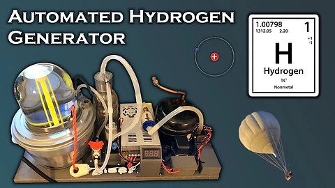
Automated Hydrogen Generator
061023 In this video I'll show how I built my Hydrogen gas generator using electrolysis of a 10% Sodium Hydroxide solution with 316 stainless steel electrodes. Unlike an "HHO" generator, this cell separates the hydrogen from the oxygen, so it can be collected in a tank for later use. In the video, I demonstrate its usefulness as a lifting gas for a camera-carrying balloon, but my ultimate goal is to liquify it with a cryocooler at -252C or use it as a working fluid in a stirling cycle to serve as a cheap and plentiful substitute for helium. I'm also interested in using it to manufacture synthetic methane by combining it with CO2 in a process known as the Sabatier reaction.
The theoretical voltage required to separate water by electrolysis is 1.23V, but in reality it will end up being 1.5-2.0 volts, depending on the electrolyte and electrode chemistry, as well as cell temperature. In order to maximize efficiency and minimize the occurance of heating and side reactions, the voltage on a cell should be kept as low above this threshold as possible. Most industrial devices have a cell voltage somewhere between 2.2-2.5 volts. The efficiency of electrolysis is approximately the threshold voltage divided by the cell voltage.
The calculation to approximate hydrogen production rate is:
Liters per hour = V_threshold * Current * 3600 / 287,000 * 24
The production rate of oxygen gas is half this amount.
One potential pitfall of hydrogen storage in pressure vessels or use as a working fluid in cryocoolers / heat engines is the tendency for atomic hydrogen to work its way into the crystal lattice of metals and cause it to become brittle, similar to how adding carbon to steel makes it more brittle. Supposedly this can be mitigated by ensuring the hydrogen gas is totally dry, and aluminum / copper seem to be far less affected by this issue than steel.
It's important to remember that if you're using stainless steel electrodes, over a long period of time, they can degrade and release toxic chromium salts into the electrolyte, some of which may be the hexavalent (Cr6+) form of Chromium. This electrolyte can't be dumped down the drain. To dispose of it properly, you need to evaporate the water and deliver the precipitate to a hazardous waste disposal site.
Aqueous solution conductivity chart:
https://pdfs.semanticscholar.org/cbc5/22cf4c5e6e690ca48984314c231f6643ee81.pdf
Music Used:
Fortaleza - Topher Mohr and Alex Elena
86
views
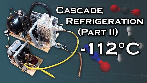
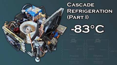
DIY Cascade Refrigeration System (Part II)
280923 This is the second part of my video series on building a DIY cascade refrigeration system, where i reach (and exceed) my goal of reaching -100C.
Part I:
https://www.youtube.com/watch?v=T76UDLPv04Y
In this video, i experiment with some alternative refrigerants for second stages. I tried CO2 (R744) (which isn't viable due to freezing) and Nitrous oxide (R744A), which is a very effective refrigerant but also potentially hazardous. I reached an open-cycle temperature of -81C with CO2 and -91C with Nitrous oxide.
Later, i figured out that the source of my hydrogen contamination in my Ethylene production wasn't from excessively hot aluminum oxide catalyst, but rather from an excessive flow rate of ethanol. There was more ethanol flowing than the catalyst could decompose in a given timeframe, and when the unreacted ethylene (which was superheated) came into contact with the copper tubing feeding the condenser, it decomposed to form acetaldehyde and hydrogen. This was the primary source of contamination.
To remedy this, i built a new ethanol boiler consisting of a well insulated 250ml flask with a load resistor placed inside. The load resistor was powered by a bench power supply which allowed precise control of the ethanol flow rate. The reactor works best with under 40W into the boiler. This is low enough to ensure the catalyst can handle all of the Ethanol.
I also removed the copper lines in the reactor and replaced them with aluminum to eliminate any possibility of having copper-catalyzed decomposition that would create hydrogen.
The lowest open-cycle temperature i achieved with Ethylene was -112C, exceeding my original goal for this project of -100C. It's possible to build a cascade refrigeration system to reach liquid nitrogen temperatures, but excessively complicated to the point of not being practical, since it would require 4 stages to work.
The next phase of this project will focus on Joule-Thompson type cooling, but instead of using pure nitrogen or air, I'll be using a mixture of Propane, Ethylene, Methane, and Nitrogen. If optimized, this scheme can exceed the performance of a conventional Joule-Thompson cryocooler by an order of magnitude, while only requiring modest pressures (20-30 bar) compared to the 200+ bar normally needed.
Once again, big thanks to Exotic Chem Lab for sharing his experience in DIY refrigeration and cryocooling to help this project succeed:
https://www.youtube.com/@Exotic_Chem_Lab
Music Used:
Kevin MacLeod - Lobby Time
82
views
Joule-Thompson Cryocooler
040723 Like and subscribe. This is an archive, check the link in the end if you are owner. Big thanks to @Exotic_Chem_Lab chem lab for sharing his experience to help make this project happen
In this video I'm going to examine the performance of a homemade cryocooler using the joule-thompson effect. A joule-thompson type device was the first method that was used to liquify nitrogen on an industrial scale, but it was very inefficient. Using nitrogen at pressures of 200-300 bar, it would drop the temperature through a regenerative heat exchanger until it reached a low enough temperature that some of the nitrogen would condense to liquid when it expanded through a flow restriction. This process was very inefficient, usually less than 1% of input power went into actually cooling and condensing the nitrogen.
I'm going to be taking a slightly different approach that's a sort of half-way between a joule-thompson device and a vapor compression system. Instead of using air or pure nitrogen as a working fluid, I'm going to use a mixture of hydrocarbon gases (propane, ethylene, and methane), which have dramatically higher joule-thompson coefficients. Unlike a traditional joule-thompson system, this type operates in a closed-loop. Typical low side temperatures get down to -160C to -170C, which is enough to liquify air or pure nitrogen if it's pressurized to 10-20 bar inside the cold end, which is trivial to do.
Higher boiling gases will condense as the temperature of the cold head is reduced and cease to contribute to the joule-thompson cooling, but still make a major contribution to heat transfer when they evaporate in the regenerative heat exchanger.
I built this system using the compressor and condenser coil from a 12K BTU portable AC unit (meaning the compressor pulls around 900W loaded). The oil separator is a temprite 900 series, and the heat exchanger consists of 30 ft (9m) of two 3/16" tubes for the high pressure side and a single 5/8" tube for the low pressure return line.
I only reached -88C in this video, because a defective oil separator was causing oil to overflow into my heat exchanger and freeze at such low temperatures, resulting in clogs in the capillary tube. The heat exchanger also wasn't properly insulated or pre-cooled in this video. With those changes, reaching -150 to -160C should be relatively easy with the correct gas composition.
Music Used
Kevin MacLeod - George Street Shuffle
Kevin MacLeod - Groove Groove
Kevin MacLeod - Lobby Time
Local Forecast - Elevator
https://rumblevideoarchive.wordpress.com/
56
views
DIY Cascade Refrigeration System (Part I)
140523 Like and subscribe. This is an archive, check the link in the end if you are owner. Big thanks to Exotic Chem Lab for providing lots of guidance / info on this project. Check out his channel at:
https://www.youtube.com/@Exotic_Chem_Lab
In this video I'll be building on the work I did in my last 2 videos (DIY vapor compression refrigeration & Ethylene Production) to create a 2-stage or "cascade" vapor compression refrigeration system that uses propylene (aka MAPP gas) in the first stage, and Ethylene (R1150) in the second stage. The goal of the project is to hit -100C.
A major snag i ran into was that I wasn't getting the temperature drop I thought i'd be getting from my Ethylene refrigerant. Running the second stage condenser below -30C and 400 psi, no condensation was occuring, despite the fact that my Ethylene should have begun condensing around ~300 psi. After some investigation, it figured out that the Ethylene refrigerant was highly contaminated (about 30%) with Hydrogen gas from running the catalyst too hot during the production process. This resulting in the partial pressure of Ethylene being reduced to the point that condensation couldn't be achieved at a reasonable total pressure.
Using a converted ice maker, i built a second cascade system where the second stage was essentially static, as opposed to a continuous loop. The purpose of this was to collect my ethylene and get it to the lowest possible temperature and condense it under pressure, then release it and hopefully allow the hydrogen to be purged out by phase separation. This allowed me to analyze the behavior of my gas mixture, and i found that at -38C, the mixture that should have condensed at around ~16 bar actually required ~23 bar to condense. This information is what allowed me to make a rough determination of the Ethylene's purity (around 70%).
Unfortunately, my attempt to purify the Ethylene through phase separation simply resulted in all of it boiling off because my flow rate was so high. However, in the process, I did manage to capture a temperature drop on my thermocouple of as low as -83C, meaning Ethylene did in fact condense in my icemaker unit and then evaporate again, so while I technically achieved cascade refrigeration, there's more work that has to be done before I can get continuous refrigeration down to -100C, which will be the focus of my next video. The two main areas of improvement are:
-Making Ethylene of a significantly higher purity (95% or higher)
-Fine tuning the second stage flow resistance / high side volume / low side volume for optimal flow rate / pressure drop
Once temperatures of -100C can be consistently achieved, it will become possible to produce Liquid Methane (or LNG), such as what's used in modern rocket engines like the SpaceX Raptor. This will be done by using a third compressor to take natural gas from a residential source and condense it at a pressure of 26 bar (370 psig) at -100C. When expanded back to 1 bar, the temperature will drop to -162C.
Music:
Kevin MacLeod - George Street Shuffle
https://rumblevideoarchive.wordpress.com/
52
views

Making Ethylene (Refrigerant R1150)
230423 Like and subscribe. This is an archive, check the link in the end if you are owner. First off, huge thanks to Exotic Chem Lab for helping me with this video. He's provided me with the valuable information I need to create my own DIY cryocooler. He just started his youtube channel, which you can find at the link below:
https://www.youtube.com/@Exotic_Chem_Lab
In this video, I'll be making Ethylene (also called "Ethene", but not to be confused with "Ethane") gas to use as a refrigerant in the second stage of a two-stage vapor-compression system.
Ethylene has the formula C2H4 (as opposed to Ethane, which is C2H6), and has a boiling point of -104C. However, at a pressure of about 16 bar, its boiling point rises to -37C. This means if i compress it to at least 16 bar and then cool it with the evaporator coil from my propane-based vapor compression system, i can force it to liquify, and then expand it in an evaporator to below -100C. This would technically qualify as cryogenic, at least according to US EPA specifications, which considers any temperature below -90C to be "cryogenic".
Typically, a cascade refrigerator would use R508 as its second stage refrigerant, but this substance is no longer produced for environmental reasons, so it's prohibitively expensive. This makes Ethylene the only practical alternative for a hobbyist. Ethylene is also sold as "R1150" refrigerant, but difficult and expensive to acquire in this form. In some countries it may require a license to buy.
Fortunately, DIY production is relatively simple. By boiling ethanol and passing the vapors over an activated alumina (Al2O3) catalyst, the ethanol molecule is dehydrated as follows: C2H6O = C2H4 (gas) + H2O (gas). The output gases are then bubbled through liquid water, and the steam condenses, leaving behind the ethylene gas.
The only catch is that the dehydration has to proceed within a certain temperature range. The optimal temperature for ethylene production is about 450C +/-50C or so. Once the catalyst drops below 350-400C, the majority of the ethanol becomes diethyl ether or (C2H5)2O. Above about 500C, the ethanol molecule starts to decompose entirely, producing pure hydrogen and pure carbon. For this reason, it's necessary to use a thermocouple in the catalyst vessel to ensure optimal temperature is maintained.
Ethylene has a very distinct smell that many people describe as "faintly sweet and musky". To me, the smell is very similar to rotting/overly ripe fruit. It quickly becomes nauseating and can cause dizziness depending on the concentration. A more serious hazard of this gas is that it has almost exactly the same density as air. This means if undisturbed, a cloud of highly flammable ethylene can sit in one spot instead of sinking to the floor like propane or floating up and escaping like methane or hydrogen.
For storage, i collected the ethylene gas in a beach ball then used a fridge compressor to force it into a 2.5 gallon (9.5L) air tank, which had been evacuated, flushed with propane multiple times, then evacuated again to ensure no explosive mixture would occur. This will then be fed into the low-pressure side of the second stage of my vapor compression system when it's built.
Music Used:
Fortaleza - Topher Mohr and Alex Elena
Lobby Time - Kevin MacLeod
Bossa Antigua - Kevin MacLeod
https://rumblevideoarchive.wordpress.com/
48
views
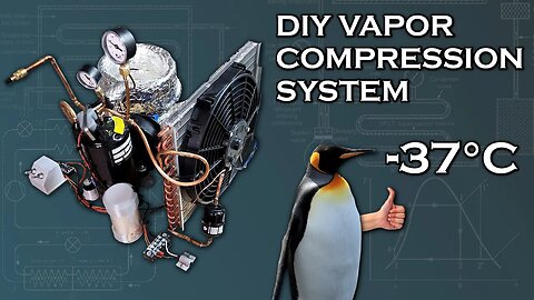
DIY Vapor Compression Refrigeration System
110423 Like and subscribe. This is an archive, check the link in the end if you are owner. In this video i'll show how to put together a single-stage vapor compression refrigeration system and explain the theory behind it. This machine uses propane (R290) as a refrigerant, because it has properties very similar to standard Hydrofluorocarbon (HFC) refrigerants, but is extremely cheap and readily available, and has almost no negative environmental effects. The obvious disadvantage is its flammability. If you're careful, though, propane or butane are perfect substances for a DIY vapor compression system.
This is still part of my long term project to build a DIY cryocooler to make my own liquid nitrogen, but I've pivoted away from gas-phase systems like stirling/GM and decided to focus more on phase change systems due to the greater availability and low cost of parts. In upcoming videos, i'll be staging multiple vapor compression loops together to get temperatures below -100C. After that, i'll use a joule-thompson cycle to make the final push down to liquid nitrogen temperatures, but will do so with a mixture of hydrocarbons rather than nitrogen.
Here's some performance specs of the device in this video:
Condenser Pressure: 10-15 bar
Condenser Temperature: 27-44 C
Evaporator Pressure: 1.2 bar
Evaporator Temperature: -37 C
Capillary tube ID: 1mm
Capillary tube length: 2m
Compressor nominal rating: 5,000 BTU
Compressor locked rotor amps: 27A
Compressor operating limit (estimated): 5.4A
Input power: 667W (529W from compressor, 138W from fans)
Refrigerant charge: ~50 grams of propane
Maximum recorded cooling power: 116W (COP 0.173)
*Note that this power was recorded by testing the temperature drop of water reservoir at room temperature with lots of heat leaks, which was a far from optimal condition.
Also, recording cooling power by multiplying the water flowrate of 13.5 grams/sec by water's heat capacity times the temperature differential across the coil of 3.3C yielded a higher cooling power of 186W.
In upcoming videos, this system will be used to cool the condensor of a second refrigeration circuit, which will then evaporate to a far colder temperature close to -100C. This requires ethylene as a refrigerant (R1150). It's pretty hard to find and expensive to buy commercially, so in the next video, i'll be showing how to make it.
Other useful tidbits:
Propane bottle NPT thread adapter:
https://www.amazon.com/Hooshing-Propane-Adapter-Throwaway-Cylinder/dp/B082MBGVXN/
Condenser fan:
https://www.amazon.com/BLACKHORSE-RACING-Universal-Electric-Radiator-Thermostat/dp/B07DLSPDN1/
-Window AC unit that was stripped for condenser coil was rated at 5,000 BTU. The manufacturer/model number you use is not important as long as its sized right.
Music Used:
Kevin MacLeod - Lobby Time
https://rumblevideoarchive.wordpress.com/
52
views

Making Dry Ice from scratch
140323 Like and subscribe. This is an archive, check the link in the end if you are owner. In this video, I'm going to show how to make dry ice (frozen CO2) from scratch. I thought using dry ice to pre-cool my pulse tube cryocooler might help me get lower temperatures, since dry ice is -79C, and adding my pulse tube's ~100C temperature drop on top of that could get me very close to liquid nitrogen temperatures. But instead of just buying dry ice, I wanted to see if it was feasible to make it myself, so I went through the steps of producing, cooling/compressing, and discharging the CO2
as liquid to form ice.
There are several ways to produce CO2 - a few of these are:
-Reacting acid with baking soda
-Cooling and collecting exhaust from combustion of hydrocarbons
-Capturing exhaust from yeast as it consumes sugar
-Capturing human breath
-Dissolving atmospheric CO2 in water and extracting it under vacuum
-Reacting atmospheric CO2 with Calcium Hydroxide, creating Calcium Carbonate, then decomposing the Calcium Carbonate to release CO2 and Calcium Oxide. The Calcium Oxide is later regenerated back into Calcium Hydroxide with sodium hydroxide.
Once the CO2 is captured, it has to be stored. In theory, large gas bags could be used, but that's not very practical, so i used a fridge compressor to force the captured gas into a compressed air tank at ~160 PSI (about 12 bar). Using a 10 gallon (38L) tank, i stored approximately 1.8 lb (0.82kg) of CO2 gas.
However, to freeze CO2, it first has to be liquified by either high pressure, very low temperatues, or both. To liquify at room temperature around 25C requires about 60 bar of pressure (~867 psi), but my compressor was only capable of producing about 400 psi (about 28 bar). In order to liquify the CO2 at this pressure, i had to put the tank in an ice bath at 0C.
Even this wasn't quite enough, though, so to get a little bit of extra pressure, i fed the output from the 12 bar tank into the suction side of my compressor, allowing it to produce close to 600 PSI at the discharge side. In the ice bath, this was enough pressure to liquify the CO2, but it took a little over an hour to transfer and condense the CO2 from the 12 bar tank. I collected about 500 grams of liquid CO2 in the high pressure tank.
Once I had the liquid CO2, i turned my high pressure tank upside down so that the liquid would come out first, and discharged it. Liquid CO2 can't exist at 1 atmosphere of pressure, so as soon as it comes out of the tank, it flash freezes to dry ice at -79C.
The tricky part is capturing the frozen CO2, since most of it blasts out into the atmosphere. The container being used to capture the ice needs to be vented to work properly, but not vented too much, or else all the CO2 will be lost. To do this, I tried a sock (effectively a porous container), which probably collected less than 20% of the CO2 from the tank as ice, and came out in a fine powder, meaning it didn't last long. The second approach used a mold with velt holes, but i only recovered about ~2% of the CO2 this way.
I think the key to creating a block of dry ice is to discharge relatively slowly into a mold. I had my valve full open, and I think instead of allowing ice to collect and settle in the mold, the flow was blasting it out.
Ultimately, the time and cost of producing the dry ice from scratch make it impractical as a pre-cooler for liquid nitrogen generation.
Music Used:
Kevin MacLeod - Lobby Time
Kevin MacLeod - George Street Shuffle
Kevin MacLeod - Groove Groove
https://rumblevideoarchive.wordpress.com/
353
views
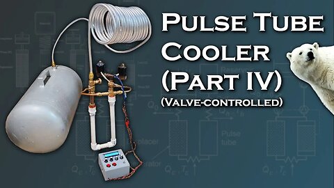
Pulse Tube Cryocooler (Part 4) - Valve Controlled
180223 Like and subscribe. This is an archive, check the link in the end if you are owner. This is the 4th part in my video series on designing/building/testing a pulse-tube cryocooler in an attempt to create low enough temperatures to liquify nitrogen (-196C or 77K). In this video, i'll be investigating an entirely different type of pulse tube that uses two valves - one connected to a compressor and another vented to the atmosphere - to create the pressure oscillations in the pulse tube. This is known as a "Gifford-McMahon" (GM)cycle, and is more commonly used in a refrigeration cycle with a moving displacer, but can also be found in use with pulse tubes.
The GM cycle is less efficient than using a piston (stirling-type) to generate pressure oscillations, but has the advantage that it's cheaper and easier to build, since it can be coupled with a variety of different compressors and matching acoustic impedance is not neccesary. GM-type cycles typically operate at a COP of under 5% of Carnot, whereas advanced stirling-type coolers can approach 30% of Carnot. Despite this, GM cycles are the primary type used in terrestrial applications, such as cryocoolers in labs and production
facilities
where modest quantities (under 10L per day) of LN2 are required. Despite the increased energy consumption, this configuration is typically cheaper to install/maintain than stirling cycle coolers, which are usually reserved for aerospace applications, like being mounted onboard sattelites or missiles to cool optics.
For the valve assembly, i used a pair of solenoid valves activated by MOSFETs which could have their timing controlled by an arduino with a front panel display, allowing me to know the exact timing I dialed in, which was very convenient for repeatability. Real GM cycle coolers use a rotary valve connected to a motor inside the pressurized assembly, which is more reliable than solenoid valves.
The entire assembly runs at around 0.5 hz. Typical commercial units range between 1-2 hz, in contrast to stirling cycle units, which can operate anywhere from 20 hz to 100 hz. However, pressure ratios are typically much higher on a GM unit, ranging from 2-3 with a baseline pressure typically from 10-30 atmospheres, whereas pressure ratios on stirling units are usually in the neighborhood of 1.1-1.3. Most GM units will have a high pressure side around 200-400 psi and a low pressure side from 50-200 psi, depending on the cold head and compressor being used.
The lowest temperature i achieved running on compressed air was -83C, but I didn't consider this a valid result, because I wasn't able to repeat it. The lowest repeatable temperatures were in the low 70's, basically matching the performance of my previous stirling-type pulse tube. Considering that the power input required was close to 1 kW, compared to the previous design's power of ~120W max., it's clear that this setup is far less efficient.
One of the major sources of inefficiency is the fact that my low-pressure side is simply connecting to the atmosphere, rather than being connected back to the compressor in a closed loop. This is because my current compressor isn't hermetically sealed, and not meant to operate with input pressures over 1 atm. With my high side pressure at 100 psi, theoretically, the most efficient low side pressure would be somewhere between 40-60 psi.
In the next part of this series, I'll be generating hydrogen and using it as a working fluid instead of air, with a closed-loop system running off a hermetically sealed fridge compressor. This will dramatically increase internal heat transfer, making the whole system more powerful and efficient, and should bring me much closer to my goal of -196C.
Part I:
https://www.youtube.com/watch?v=GjRoThMyNGA
Part II:
https://www.youtube.com/watch?v=WOmjJFk8rl0
Part III:
https://www.youtube.com/watch?v=cy8aGMH8Tz4
Music Used:
Kevin MacLeod - Lobby Time
Kevin MacLeod - George Street Shuffle
https://rumblevideoarchive.wordpress.com/
129
views
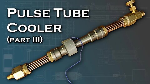
Pulse Tube Cryocooler (Part 3)
210123 Like and subscribe. This is an archive, check the link in the end if you are owner. This is the third video in my series on building/testing a Pulse Tube cryocooler with the eventual goal of liquifying nitrogen/oxygen.
Part I:
https://www.youtube.com/watch?v=GjRoThMyNGA
Part II:
https://www.youtube.com/watch?v=WOmjJFk8rl0
In this video I investigated the effects of different pulse tube materials, regenerator materials, heat sink designs, inertance tube geometry, and pressurization of the working fluid. While I didn't manage to exceed my record from the previous video of -75C drop (corresponding to a drop below ambient of about 100C), I did gather a lot of information about design factors.
My initial design in this video used a stainless steel pulse tube/regenerator housing, but i found that the temperature difference generated for a given power input was dramatically lower than with PVC parts due to conduction losses.
One of the biggest takeaways from the tests i ran was that performance is almost directly proportional to the pressurization of the working fluid, and having a large average pressure is much more important than having a high compression ratio. This is consistent with how real cryocoolers are built, which are typically pressurized anywhere from 10 to 30 atmospheres, but have pressure oscillations of under 10% of average pressure.
I also experimented with different regenerator materials, such as ceramic beads, glass beads, plastic pellets, and glass fibers, but found that compacted stainless steel wool (which i started with) still performed best.
For configurations both with the 25mm diameter piston and the 40mm diameter, i found that the cooler seemed to hit a wall at around ~100 degrees of temperature drop below ambient, where application of additional power only marginally improved performance. I suspected this was related to limitations imposed by the inertance tube and compared my 1/4" copper tubing against 3/8" flexible silicone tubing of a greater length, but I found that this change reduced performance, most likely due to increased surface roughness and flexibility in the line dissipating energy. In a future video I'll probably try to use rigid copper/aluminum tubing with a 3/8" or 1/2" inner diameter.
I also reconfigured the entire device into an alpha-type stirling cooler, but found that performance was actually dramatically reduced despite the ability to mechanically set the phase angle between compression and expansion. I think this is because the cold expander piston was causing large conduction losses through its thin aluminum walls.
I ran the device with loads disconnected, and with pistons disconnected to determine the amount of power being consumed by mechanical action as opposed to pneumatic power, and found that less than 30% of the input electrical power was actually going into the system.
Finally, I examined the effect of a double-inlet valve, which has the effect of improving phase shift and removing some of the load on the regenerator. While this didn't make a tremendous difference, the difference is very obviously apparent and repeatable.
In my next video, I'm going to build an entirely different test setup using a valve-based (or "Gifford-McMahon") configuration and a standard air compressor as a high pressure source. While this configuration is less efficient, because the input power would be so much larger, it should be an overall net positive. In addition, control over valves allows me to achieve consistent timing via digital control and fine tune it for best performance.
https://rumblevideoarchive.wordpress.com/
68
views
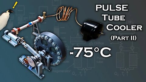
Pulse Tube Cryocooler - Part 2 (-75C)
271222 Like and subscribe. This is an archive, check the link in the end if you are owner. Part 1:
https://www.youtube.com/watch?v=GjRoThMyNGA
This is the second part of my video series on attempting to build a Pulse Tube cryocooler. I managed to make significant progress by removing the linear motor and using a conventional rotary motor with a large gear reduction ratio and a flywheel to produce the larger forces needed for higher compression ratios.
For pistons, I used pneumatic actuators. I evaluated a 25mm bore and a 40mm bore piston, both with a 50mm stroke. Pneumatic actuators have more friction than conventional pistons due to their rubber lip seals, but theoretically have zero blowby, so they hold pressure, which makes them more effective for low frequency applications.
Here are some specifications for the cooler:
Pipe diameter: 18mm
Regenerator Length: 30mm
Regenerator Material: Fine steel wool
Pulse Tube Length: 100mm
Flow resistance source: 1/8 NPT needle valve
Inertance Tube Length: 10' (~3m)
Inertance Tube Diameter: 4.4mm
Buffer Tank Volume: 2L
Piston Swept volume (25mm): 23CC
Piston Swept volume (40mm): 57CC
Compression Ratio (25mm): 1.4
Compression Ratio (40mm): 2.0
Maximum Frequency: 15 Hz
Motor KV: 750
Motor Voltage: 16V
Motor reduction ratio: 5:1
Flywheel moment of Inertia: 0.012 kgm^2
Maximum recorded temperature drop below ambient: -91C
Lowest recorded temperature: -75C
I think with some more optimization, this system can probably reach -100C, although without helium or hydrogen as a working fluid, I think it's unlikely that I'll reach cold enough temperatures to liquefy oxygen/nitrogen.
In part 3 of this video, I'll do more investigation into hot-end heat exchanger design, regenerator design, and the effect of increasing the power density of the system by pressurizing it. I'll also be comparing the pulse tube performance to a similar spec alpha stirling cooler.
Links for parts:
Motor:
https://www.amazon.com/dp/B084QCLTM1?psc=1&ref=ppx_yo2ov_dt_b_product_details
25: and 40mm pistons:
https://www.amazon.com/gp/product/B082FW5XKS/ref=ppx_yo_dt_b_search_asin_title?ie=UTF8&th=1
https://www.amazon.com/dp/B08YYQZ5CQ?ref=ppx_yo2ov_dt_b_product_details&th=1
Music Used:
Kevin MacLeod - Lobby Time
Kevin MacLeod - Groove Groove
https://rumblevideoarchive.wordpress.com/
75
views
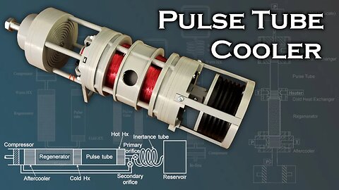
Pulse Tube Cryocooler - Part 1
081222 Like and subscribe. This is an archive, check the link in the end if you are owner. In this video i expand on the resonant linear motor from my previous video and use it to drive a linear compressor for a pulse-tube refrigerator. A pulse tube refrigerator is used to reach cryogenic temperatures, with some going into the sub-kelvin temperature range. These are typically used in labs for scientific experiments that require extreme low temperatures, or for sensors on sattelites/spacecraft, like the optics on the James Webb Space Telescope.
From a thermodynamic standpoint, a pulse tube cryocooler is effectively the same as a Stirling or Gifford-McMahon (GM) cooling cycle, but it replaces the displacer (or expander piston in the case of an alpha-stirling) with a gas piston. With careful tuning of a needle valve, inertance tube (gas momentum tube), and buffer volume, the phase of the gas piston's motion is shifted from the pressure oscillations of the compressor (by ~60-90 degrees), allowing heat pumping to occur out of the cold end. The major advantage of this device is that it eliminates moving parts from the cold end, which would be the displacer piston in the case of a Stirling or GM cooling cycle.
While i did manage to create a working linear compressor with a tuned dynamic balancer to create pressure oscillations, the linear motor didn't seem to have enough force to create a reasonably large compression ratio, and i only managed to produce a minor temperature difference. However, actuating the piston by hand, i was able to produce a temperature drop of around 4C.
Pulse tubes are also extremely dependent on the tuning of the needle valve, inertance tube, and buffer volume, which act like an electrical RLC circuit to create a specific phase shift at a specific frequency. The pneumatic tuning in this video was far from optimal.
In the next part of this series, i'll be replacing the linear compressor with a rotary compressor that I plan to build with an air cylinder driven by a geared down brushless motor from an RC plane. I'll also be focusing heavily on tuning the inertance tube / buffer volume, and optimizing heat exchangers to remove energy from the system even at small temperature differentials.
Previous video on building a linear motor:
https://www.youtube.com/watch?v=u7k2wiY4Flo&t=11s
If you want to understand the basics of different cryocooler types, these articles are helpful:
https://www2.jpl.nasa.gov/adv_tech/coolers/Cool_ppr/CEC2005%2050yr%20History%20of%20Cryo%20in%20Space.pdf
https://www2.jpl.nasa.gov/adv_tech/coolers/Cool_ppr/Chap%206-Refrig%20Sys%20for%20Achiev%20Cryo%20Temps_2016.pdf
This is a helpful overview of how different pulse tube configurations work:
http://large.stanford.edu/courses/2007/ph210/bert2/
This paper explains more about the math in computing resistance/inertance/compliance and phase shift:
https://trc.nist.gov/cryogenics/Papers/Pulse_Tube_Cryocoolers/2006-Inertance_Tube_Optimization.pdf
Another resource i found tremendously useful was https://cryocooler.org/. Under "Past Proceedings - Volumes 14 to 20" you can select a volume and under "Table of Contents" there's dozens of research papers on Stirling/GM/Pulse Tube cryocooler development.
STL Files (these are for the linear compressor with the TPU bellows piston):
https://www.thingiverse.com/thing:5684574
Music Used:
Heatley Bros - Sunset Beach
Kevin MacLeod - George Street Shuffle
Kevin MacLeod - Lobby Time
https://rumblevideoarchive.wordpress.com/
432
views
1
comment
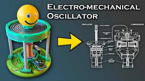
Electro-Mechanical Resonant Oscillator
011122 Like and subscribe. This is an archive, check the link in the end if you are owner. In this video I'll show how to build a resonant mechanical oscillator that's driven by an electromagnet. The electromagnet is pulsed by a circuit
with an adjustable frequency, so it can be fine tuned to run at the exact resonant frequency of the spring-mass system. In this case that
frequency is about 11 Hz. The driver basically just consists of a 555 timer and a MOSFET to turn the coil on and off. In the future, i think i
need to use a feedback controller to do this, because even when i get the system to resonate, it eventually drifts out of phase and resonance
dies off (even though the frequency is matched).
This type of device is commonly found in the compressor section of compact cryocoolers for infrared imaging and other sensors that require
extremely cold temperatures to operate. Suspending the compressor pistons on a flat spring or "flex bearing" and driving them at resonance allows
for high power and efficiency even with the relatively weak forces between the magnets and the coils. This is analogous to a flywheel on a
crankshaft, but is lighter, smaller, and more reliable. By avoiding the need for the bearings and linkages present in a rotary system, this kind
of devbice can achieve an extremely long service life (some are rated for over 200,000 hours of operation) inside a hermetically sealed unit.
This is part of my investigation into building my own refrigeration system (and eventually cryocooler) without HFC's/phase change refrigerants.
Several months ago i made a video showing how i built a compressed air turbine which I intended to use as a Brayton cycle cooler, and while it
did work, the extremely loud noise made it impractical in a home environment, so I'm now investigating reciprocating systems like Stirling/Pulse
Tube/Thermoacoustic/Gifford-McMahon-type devices for generating extremely low temperatures.
Music Used:
Kevin MacLeod - George Street Shuffle
Kevin MacLeod - Groove Groove (Yes, this is the same song that's in Kerbal Space Program)
STL Files:
https://www.thingiverse.com/thing:5594081
Metal Spring DXF file:
https://drive.google.com/file/d/1OX4CL7d9jAzPwvoHF9XoKwuRwrusV23V/view?usp=share_link
Driver circuit schematic:
https://drive.google.com/file/d/1chrHYzkV6LTJ1hQsXgQ6WjCTgmVXKFEx/view?usp=share_link
Further reading on cryocoolers:
https://www2.jpl.nasa.gov/adv_tech/coolers/Cool_ppr/CEC2005%2050yr%20History%20of%20Cryo%20in%20Space.pdf
https://www2.jpl.nasa.gov/adv_tech/coolers/Cool_ppr/Chap%206-Refrig%20Sys%20for%20Achiev%20Cryo%20Temps_2016.pdf
Fabrication shop i used for the metal springs:
https://sendcutsend.com/
https://rumblevideoarchive.wordpress.com/
47
views

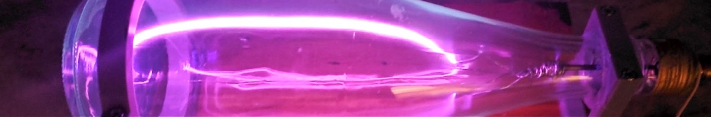
Corona Discharge Photography
071022 Like and subscribe. This is an archive, check the link in the end if you are owner. In this video I'll show the technique of "Kirlian Photography", which uses corona discharge off a conductive object for imaging. The technique uses two clear glass plates with salt water between them. The salt water is connected to a high voltage, high frequency AC source. An AC flyback transformer works for this, but i got better results using a solid state tesla coil operating off a slayer exciter circuit - the same circuit i demonstrated in my previous video. This generates around 40,000 volts at 350 kHz with a 12V input.
The high voltage AC doesn't conduct through the glass, but causes high voltage charges to appear on the outside surface of the glass plates through capacitave coupling. Because glass is an electrical insulator, the charges can't move freely along the surface, so when an electrode connected to ground comes near the glass, the resulting discharge "fans" out, as charges from a relatively large area will jump to a single point electrode.
When a flat conductive object is pressed against the glass, the edges and small bumps on its surface will exhibit this type of discharge and glow purple. Since the glass plates and the saltwater are transparent, the resulting glow can easily be photographed.
This results in some extremely interesting and visually impressive effects, but is mostly limited to flat conductive objects like coins, keys, blades, etc.
I've seen some videos that use acrylic insulators for doing this - which I strongly advise against, because the discharges will heat up and melt the acrylic - leaving a permanent mark or even burning a hole through the sheet.
Also, if you want to do this project and you're building an AC flyback, be mindful of the secondary coil inductance and its resonant frequency. I found that by having an enormous turns ratio at a high frequency, the transformer operating frequency was actually well above the resonant frequency between the coil and any parasitic capacitance - which causes tremendous losses and erratic performance - this problem is avoided with the solid state tesla coil.
Music Used:
Serge Pavkin - To the Stars
Serge Pavkin - Atmospheric Ambient
Serge Pavkin - Andromeda
Serge Pavkin - Cosmic Glow
https://rumblevideoarchive.wordpress.com/
57
views

Tabletop Tesla Coil
180922 Like and subscribe. This is an archive, check the link in the end if you are owner. In this video I'll show how i built a battery powered solid state tesla coil that fits on a desk or a coffee table. The coil uses a "slayer
exciter" circuit with an RC snubber and reverse protection diode to avoid damaging spikes of voltage/current during "hard switching". In
addition, 3 FETs are used in parallel to spread out the heat load, which makes the circuit far more reliable.
In addition to those changes, I've buffered the MOSFET gate drive with a push-pull pair consisting of an NPN and PNP transistor. This allows the
gate to be turned on and off much faster, and allows more control over the gate voltage by using a resistor divider on the base of the
transistor(s).
The circuit is interrupted with a 555 timer. It runs at approximately 60 hz and 30% duty cycle. This gives the arcs a more sharp/jagged shape,
but also reduces the power consumption and heat load.
Another useful feature in this driver is the low voltage cutoff circuit, which shuts off the gate drive transistors if the supply voltage falls
below 22V. This ensures that the lithium battery won't be over-discharged.
The maximum arc length i've observed on this coil is approximately 4" (10 cm),
which is very impressive considering that the supply voltage is only 24V.
You may have also noticed that I used a sharp electrode for a breakout but no toroidal / spherical top load. This is to reduce
A few specs:
Primary Turns: 2
Secondary Turns: ~1200
Secondary Diameter: 3.5"
Secondary Height: 6.0"
Input Voltage: 24V (Nominal)
Current Consumption: ~4A
Operating Frequency: ~300 kHz
Interrupter Frequency: ~60 Hz
Duty Cycle: 30%
Snubber R/C: 2 Ohm / 54 nF
Parts I used:
IRF640 (3 in parallel for driving the primary)
2N3904 / 2N3906 (gate drive transistors)
2N3904 for undervoltage cutoff / interrupter pull down
MUR120G (Rail diodes)
NE555 (Interrupter)
LM833 (Undervoltage cutoff comparator)
Music Used:
Kevin MacLeod - George Street Shuffle
Kevin MacLeod - Lobby Time
Serge Pavkin - Crystals
https://rumblevideoarchive.wordpress.com/
48
views
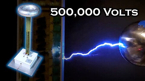
500,000 Volt Lightning Tower
040922 Like and subscribe. This is an archive, check the link in the end if you are owner. In this video I'll show how i use a diode-capacitor chain to boost 9,000 volts AC to over 500,000 volts DC. This is known as a "Cockroft-Walton" type generator, and was used to generate high energy discharges for early particle accelerators.
It looks very similar to a Tesla coil, but it's sort of the exact opposite, because it outputs DC instead of AC. This gives it a unique capability that a Tesla coil doesn't have - it can produce static electricity. In fact, at 500kV, some objects can be given enough static charge to repel each other like magnets. It'll pull your hair toward it from across the room - similar to a Van de Graaf generator, but much more powerful.
The input to the multiplier is 9,000 volts peak at around 50 kHz from a flyback transformer i wound myself being driven by a ZVS driver with a 24-volt supply from a 6S LiPo battery. I've covered the ZVS driver in several of my other videos, so I didn't bother to do so in this one.
If you're thinking of recreating this project, just keep in mind that a discharge from this device is far more dangerous than an arc from a Tesla coil. The current from a Tesla coil will travel along the outer surface of your skin because of the high frequency AC - usually in the hundreds of kHz. The DC discharge from this multiplier will go straight through your body. Always make sure to use a long, non-conductive (DO NOT use wood!!) stick with a solid connection to ground when you're making arcs, and when you're finished, keep the electrodes shorted together for a minute or so to ensure any residual charge has bled off.
Capacitors and diodes are just cheap units off of amazon:
20 kV / 100 mA diodes:
https://www.amazon.com/2CL2FM-100mA-Voltage-Diode-Rectifier/dp/B074S8JT96/
20 kV / 1 nF capacitors
https://www.amazon.com/dp/B07V3XMHHL
Music Used:
Kevin MacLeod - Lobby Time
Kevin MacLeod - Hard Boiled
Kevin MacLeod - Groove Groove
https://rumblevideoarchive.wordpress.com/
65
views
2
comments
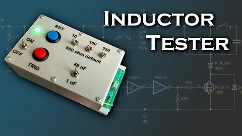
Inductor Tester
050822 Like and subscribe. This is an archive, check the link in the end if you are owner. In this video i show how to build a circuit that can measure the value of an inductor in conjunction with an oscilloscope. This is meant to be a replacement for my $10 LCR meter, which isn't very accurate, and has very poor resolution below ~1mH of inductance.
The circuit works by sending a single pulse through an inductor, which has a known capacitance in parallel with it. When current through the inductor is shut off, the L-C pair "rings" at its resonant frequency, determined by f = 1/[2pi*sqrt(LC)]. Since frequency "F" and capacitance "C" are known, the inductance can be determined.
Current through the inductor under test is limited by current limiting resistor(s), which are manually configured by toggle switches. By default, a 680 ohm resistor is connected in series with the inductor, but 220, 100, and 10 ohm resistors can be toggled as well to allow more current for the test pulse. This is because smaller inductor values need to be pulsed with a larger current to generate a readable "ringing" signal, due to their lower energy storage for a given current.
In addition to multiple resistor options, there are two capacitance values that can be tested against. By default, a 1 nF capacitor is connected in parallel with the inductor under test, but a 47 nF can be added in parallel by toggling a switch.
If you don't have an oscilloscope, it may also be possible to measure frequency using a high impedance AC coupling to a schmitt trigger which would send square wave pulses to an arduino or similar microcontroller to be measured.
This is a valuable addition to any power electronics toolkit, because inductors/chokes and transformers are used so often, and knowing the exact component values is crucial for design optimization.
However, if you're only looking for something to give you a rough approximation of inductance / capacitance, the cheap amazon/ebay LCR meters will still get the job done, and I've used this one for several years:
https://www.amazon.com/AITRIP-Transistor-Capacitance-Capacitors-Thyristors/dp/B091356Q9T/
Automatic coil winder video:
https://www.youtube.com/watch?v=GJcQfJ6JTZg&t=419s
Music Used:
Lakey Inspired - Chill Day
Lukrembo - This is for you
Kevin MacLeod - Lobby Time
https://rumblevideoarchive.wordpress.com/
31
views
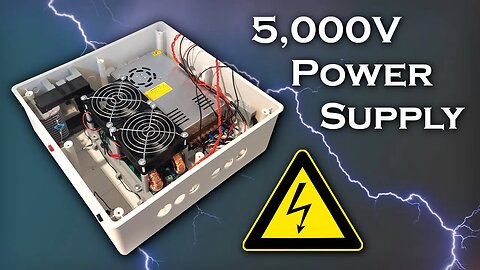
5,000 Volt Power Supply
240722 Like and subscribe. This is an archive, check the link in the end if you are owner. In this video I'll show how i built a 5,000 volt power supply. A 48V DC supply inside the box powers a ZVS driver that runs a transformer at 50 kHz. A 200 pF capacitor is placed in series with the transformer output as a power limiter, causing an output impedance of 16 kΩ. This is a really versatile supply, because i have relatively high voltage, high frequency, and a high power output from the transformer (depending on the series capacitor, it could probably output close to 600W safely).
One of the biggest snags of this project was getting the ferrite chokes at the input of the ZVS driver to cooperate. If you have the wrong core material, or the chokes are under-spec'd, the driver will be unstable and go into "latch up" where one of the MOSFETs gets stuck ON, and quickly destroys itself from the heat of short circuiting.
Another issue i discovered was that it's not a good idea to have a transformer over 5kV without having the secondary submerged/potted in some sort of insulator to keep the high voltage from jumping from one winding to another (or to other objects).
Here's some of the parts i used if you want to try building it yourself:
12"x12"x4" Plastic Box:
https://www.amazon.com/dp/B08RJ3GGDZ
48V 12.5A Power Supply:
https://www.amazon.com/gp/product/B079D916WY
Big ferrite transformer core:
https://www.amazon.com/gp/product/B014A9GBRM
24 AWG Magnet Wire:
https://www.amazon.com/BNTECHGO-AWG-Magnet-Wire-Transformers/dp/B01NBM0MB5
20KV 100mA Diodes:
https://www.amazon.com/dp/B074S8JT96
20KV 1nF Capacitors:
https://www.amazon.com/Voltage-Ceramic-Capacitor-0-001uF-1000pF/dp/B07K6PH4SR
Other Components:
MOSFETs:
SIHG25N40D-GE3
400V / 25A Max 0.14Ω RDS
Gate Diodes:
UF4004
400V / 1A Fast Diode
Music Used:
Kevin MacLeod - Lobby Time
Kevin MacLeod - George Street Shuffle
Kevin MacLeod - Groove Groove
Serge Pavkin - Star Twinkle
https://rumblevideoarchive.wordpress.com/
43
views

Magnetic Remote Control
110722 Like and subscribe. This is an archive, check the link in the end if you are owner. In this video I'll show how I built a remote control that works entirely off the magnetic field of a coil (unlike a typical radio transmitter). This is known as inductive coupling, an is the same principle used in a transformer. The only difference in this case is that the windings of the transformer are very far apart. This type of signaling is common in short-range, low power devices, like RFID.
This is effectively the same setup that would be used for wireless power transfer, but with two key differences:
-The output of the transmitting coil is not a continuous wave; it's modulated to produce a signal
-The signal of the reciever coil is amplified (by about +70 dB)
The transmitter produces a series of damped oscillations at 69 kHz, with a pulse frequency that can be varied between 1.3 kHz and 2.3 kHz.
The reciever circuit the same design as you'd find in a simple AM radio, the only difference being that the frequency used here (69 kHz) is far below the AM band. The reciever extracts the signal tone, and cleans it up through a schmitt trigger to produce a 0-5V square wave. The schmitt trigger output is sent to an Arduino Uno, which reads the tone frequency, and controls a standard R/C toy servo accordingly.
The main advantage of this kind of transmitter is that it can be made to work without the huge antennas or elaborate grounding schemes needed to operate a typical ULF/VLF radio. The disadvantages are that it's very directional (on both the transmitter and reciever end), and the signal amplitude drops off exponentially faster than a typical radio. With an ideal omnidirectional radio transmission, the amplitude drops off with the square of the distance, whereas with inductive coupling, the drop off is approximately the 3.5th power of distance.
Relevant components in these circuits:
-IRLZ44 MOSFET
-NE555 Timer
-2N3904 and 2N3906 NPN and PNP BJT's
-1N4148 Diodes
-LM7805 for 5V Regulation
-15 to 365 pF Variable Capacitor for Reciever Tuning
https://www.amazon.com/Capacitor-Variable-Single-365-Rotation/dp/B00EQI9K9O/
Music Used:
Kevin MacLeod - Groove Groove
Kevin MacLeod - George Street Shuffle
Heatley Bros. - Otherworld
Lukrembo - This is for you
https://rumblevideoarchive.wordpress.com/
47
views
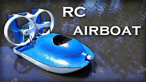
RC Airboat with a Water Cannon
250622 Like and subscribe. This is an archive, check the link in the end if you are owner. STL Files:
https://www.thingiverse.com/thing:5418100
In this video I'll show how i built an RC airboat for racing. The boat can travel on water, tile floor, and wet grass. It's powered by a 3S LiPo Battery (12V) turning a pair of counter-rotating brushlesss motors with 6" 3-bladed propellers. It's also equipped with a pump draw water from beneath the hull and shoot it out a nozzle at the front of the boat to knock over other racers.
I originally equipped the boat with an audio amplifier to play music as a gimmick, but i found that it added unneccesary weight and complexity, and couldn't be heard over the sound of the propellers, so I removed it.
The Hull is made from 3d printed sections that are glued together and smoothed out with body filler and epoxy resin. I hand-painted the parts instead of spray painting because I had a large supply of acrylic paints for arts and crafts.
Specifications (to the best of my knowledge):
Battery: 3S / 2200 mAh
Motors: 1400 kV
ESCs: 30A
Propeller: 6" / 3 blade / Pitch Unknown
Max. Current Draw: 22A
Water Cannon: 80 PSI / 4LPM / 4mm Nozzle
Here's the links to the part/ 4s I used if you want to build this or a similar craft:
Motors & ESC Combo:
https://www.amazon.com/gp/product/B00PXVG7VM/
Battery:
https://www.amazon.com/gp/product/B08H7RGZB6/
Radio Transmitter/Reciever:
https://www.amazon.com/dp/B0744DPPL8
Water Cannon Pump:
https://www.amazon.com/dp/B01N75ZIXF
Music Used:
Lukrembo - This is for You
Kevin MacLeod - Lobby Time
Lakey Inspired - Chill Day
Kevin MacLeod - Hard Boiled
https://rumblevideoarchive.wordpress.com/
31
views
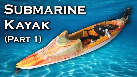
Submarine Kayak - Part 1
080123 Like and subscribe. This is an archive, check the link in the end if you are owner. This is the first video in my series on converting a kayak into a wet submarine. I found that my original submarine was a hassle to operate, because it required a heavy trailer and had to be launched from a boat ramp. This made it difficult to accomplish my goal of diving on coral reefs in the ocean, because most boat ramps are usually several miles from inlets, and inlet crossings were hazardous in the large, slow submarine.
On the other hand, this specially modified kayak is lightweight and portable. I can load it in the back of my truck, and drag it across a beach, or even through the jungle to reach springs farther inland in Florida. It will function as an ordinary kayak on the surface - being propelled either by rowing or with a trolling motor, and then submerge. Ideally, it'll be neutrally bouyant when submerged, and control its depth with dive planes. Flexible ballast bags and a powerful bilge pump will be used to return to the surface.
Original Submarine:
https://www.youtube.com/watch?v=GUOHjON9RVg&t=687s
Arduino Code for Throttle Control:
https://drive.google.com/file/d/16FM2rn-7kcdCzos7gkxweNwvR65CfFEg/view?usp=sharing
Additional Info:
Original Kayak: Pelican Trailblazer 100 NXT
Material: "RAM-X", which is a variant of HDPE plastic
Motor: Newport 36 lb saltwater trolling motor
Battery Voltage: 12V
Battery Capacity: 50 AH
ESC: Hobbywing WP1080
ESC Control: Arduino Uno
Air Capacity: 120 cubic ft @ 4,000 psi
Music:
Kevin MacLeod - George Street Shuffle
Kevin MacLeod - Groove Groove
Prod Riddiman - Lost Time
Heatley Bros. - Otherworld
Heatley Bros. - 8 Bit Chillout
https://rumblevideoarchive.wordpress.com/
133
views

Comparing Turbine Rotors
270422 Like and subscribe. This is an archive, check the link in the end if you are owner. NOTE: There's an error in the graphs where i label 20.1W as the max power on a data point below 20W. This was because i accidently clipped the Y-axis at 20W, but the maximum power was in fact 20.1W
This is the second part of my video on building a 3d printed compressed air turbine, which you can find here:
https://www.youtube.com/watch?v=Yg5swK_AnbU
In this video I'll be experimenting to find the best rotor and casing geometry for a 2D-flow turbine. I'm focusing on 2D flow because of the relative ease of machining parts, since I eventually plan to build one of these out of aluminum or brass to power with steam.
All the tests are conducted at 50 PSI with a 1/16" nozzle.
Another goal of this project is to see if it's feasible to use a 3d-printed turbine for Brayton cycle refrigeration (like the ACM on an airliner does). This requires extracting energy from the compressed air in the form of mechanical work to drop its temperature, so a more efficient turbine will have more cooling power (and provide more mechanical output to drive auxiliary devices like a secondary compressor).
Overall, my best configuration achieved a ~20% improvement over my last video, but there's a relatively large amount of scatter in my data, probably due to vibration and temperature dependance. Some further improvements I still haven't looked at are:
-Tighter tolerances between the turbine rotor and casing
-A convergent/divergent nozzle to convert more of the pressure energy to kinetic energy
-Better seals to prevent pressure leakage between stages (or to the outside).
Music Used:
Kevin MacLeod - Groove Groove
https://rumblevideoarchive.wordpress.com/
21
views
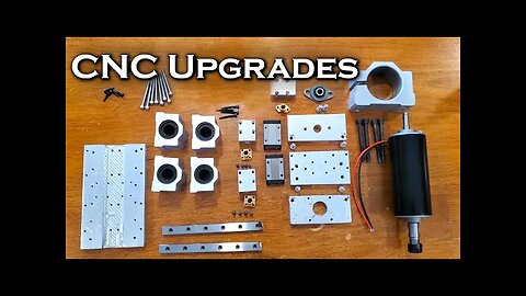
Upgrading my Homemade CNC
250322 Like and subscribe. This is an archive, check the link in the end if you are owner. In this video I'll show the upgrades I made to the CNC mill i built in my previous video:
https://www.youtube.com/watch?v=R29G3hUiZnU&t=60s
I upgraded to a 500W spindle and built an all-aluminum head assembly, widened the bed, increased the rigidity of the X axis with thicker rails,
installed higher torque steppers on X and Z, and dramatically reduced backlash on all axes by using a double-nut arrangement on my leadscrew
carriages.
The machine is still far from perfect, but cutting aluminum is significantly easier now, and with some adjustments / tightening down / tuning, I
think it will be able to reliably hold tolerances that are at least good enough for one-off hobby projects.
Currently the most obvious weakness is flexibility in the Y axis due to using only 8mm rails.
The board firmware is unchanged from the previous video. I'm still using an arduino Uno with GRBL firmware driving A4988 stepper controllers.
Some links to relevant hardware:
500W Spindle kit:
https://www.amazon.com/gp/product/B01LNBOCDA/
92 oz-in Stepper Motors:
https://www.amazon.com/gp/product/B00PNEQUZ2/
16x500 mm Linear Motion Shafts:
https://www.amazon.com/gp/product/B07ZK8Z2HS/
16mm Bore Linear Bearing Blocks:
https://www.amazon.com/gp/product/B07GQVBYYG/
Linear rail for Z axis:
https://www.amazon.com/gp/product/B086QKJ87B/
500mm T8x8 Leadscrew:
https://www.amazon.com/gp/product/B08JPMH4V9/
150x70x9.5 Heatsink:
https://www.amazon.com/gp/product/B08T8837ZH/
Software used for CNC:
Universal Gcode sender
FreeCAD 0.18
STL Files:
https://www.thingiverse.com/thing:5329372
Feeds/Speeds
RPM: 12,000
Bit: 1/8" 2 Flute End Mill
Horizontal Feed: Between 500 - 1500 mm/min
Vertical Feed: 10 mm/min
Stepdown/Cut Depth = 0.05mm
Finishing Cut Depth = 0.01mm
I found that for the same amount of volumetric removal rate, a higher horizontal speed with a smaller depth of cut gave better results because of
reduced chatter/vibration. For example, 1500 mm/min at 0.05mm depth of cut was much smoother and had less chatter than 750 mm/min at 0.10 mm
depth of cut. Unfortunately this does put all the work on the very tip of the end mill, but because this machine is pretty limited on
power/rigidity, that's the only viable way to cut.
Music Used:
Eric Skiff - Underclocked
Kevin MacLeod - Groove Groove
Heatley Bros. - Luminare
Serge Pavkin - Elevation
https://rumblevideoarchive.wordpress.com/
27
views
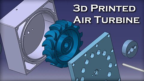
3d Printed Compressed Air Turbine
100422 Like and subscribe. This is an archive, check the link in the end if you are owner. In this video I'll experiment with some designs for a 3d printed compressed air turbine. I started this project because I wanted to research better designs for steam turbines without spending the time and money required to CNC the parts out of metal, and i got results that were almost good enough to be usable for a light duty shop tool. The highest power i measured with a simple 2D turbine on 50 PSI was 16.4 watts. I did all my power measurements with a magnetic dyno.
I also built an aftercooler to remove some moisture out of the air, because I eventually want to use a compressed air turbine for the expansion phase of a brayton refrigeration cycle for cryogenic cooling (if i can get the turbine efficient enough).
Both turbine designs i tried in the video use a 1/16" diameter nozzle insert that's CNC'ed out of aluminum. The results at the end of the video are both shown at 50 PSI.
STL Files:
https://www.thingiverse.com/thing:5347515
Music:
Kevin MacLeod - Groove Groove
Eric Skiff - Underclocked
Kevin MacLeod - George Street Shuffle
https://rumblevideoarchive.wordpress.com/
22
views