

CNC Mill for under $100
190422 Like and subscribe. This is an archive, check the link in the end if you are owner. In this video I'm going to show how I built a basic CNC mill. Most of the hardware was sourced from spare / leftover parts I had laying around from other projects and ended up costing me under $100. It has a working area of approximately 250mm x 250mm x 70mm and is capable of milling aluminum (though somewhat rough).
The axes are moved with small NEMA17 stepper motors running at 24V, driven by A4988 drivers. The brain of the machine is an Arduino Uno running GRBL firmware, and G-code is sent to it via. USB from a laptop running Universal Gcode Sender - so everything is open source.
I have a little bit of experience operating a CNC mill, but this is the first one i've built / owned. The biggest learning experience from this build was that everything needs to be tightened up and made as rigid as possible to get good results. Between leadscrew backlash and rails flexing, the spindle could easily be moved +/- 1mm or more, which causes tons of vibration, chattering, rough cutting, and loss of precision. In a future video I'll be upgrading the spindle and beefing up the structure to use 16mm rails instead of 8mm for better rigidity.
I don't recommend trying to build this design yourself, because I created the printed brackets based on parts i had on hand, not what was "optimal". However, if you really want to, the STL's can be found here:
https://www.thingiverse.com/thing:5262097
Music Used:
Kevin MacLeod - George Street Shuffle
Serge Pavkin - Atmospheric Ambient
Kevin MacLeod - Groove Groove
Eric Skiff - Underclocked
Serge Pavkin - Fractal
https://rumblevideoarchive.wordpress.com/
34
views

A Generator built from a Stepper Motor and Supercapacitors
130222 Like and subscribe. This is an archive, check the link in the end if you are owner. In this video I'll show how i used a NEMA17 stepper motor as a hand-cranked generator to charge a supercapacitor bank, which can then be used to power all sorts of things like lights, radios, or even start a fire for a survival situation.
I found that using a stepper motor as a generator was far more effective than trying to build my own with magnets and coils. With a 3:1 overdrive on this small NEMA17 motor, I could easily generate 15-20V open circuit, or sustain around 2 watts of output without much trouble.
The generator uses a pair of parallel bridge rectifiers (one for each coil set on the stepper) to charge a supercapacitor bank to 5.4V. It takes about 130-150 turns to fully charge a 16.5F capacitor bank, which can be done in under one minute, and keep the main light on for close to 10 minutes.
To protect the capacitors against overcharging, i built a circuit using an op-amp comparator to turn on a MOSFET when the capacitor voltage goes above 5.3V and short the capacitors to prevent overvoltage. I found this to be a more effective solution than simply using a zener diode.
Notable Hardware:
-NEMA17 Stepper motor. Exact model doesn't really matter (i found mine in a junk drawer).
-GT2 belt & Pulley, 60T and 20T:
https://www.amazon.com/Zeberoxyz-Synchronous-Aluminum-Timing-20-60T-8B-6/dp/B08QZ4365D
-470F / 2.7V Supercaps are Illinois Capacitor model# DGH477Q2R7
-3.3F / 2.7V Supercaps:
https://www.amazon.com/MCIGICM-Capacitor-capacitance-tachograph-Electromechanical/dp/B07BLQGRQY/
-Bridge rectifiers were GBU808 harvested from random scrap devices. Really any bridge rectifier should work for this application, though.
STL Files:
https://www.thingiverse.com/thing:5241682
Music Used:
Kevin MacLeod - George Street Shuffle
https://rumblevideoarchive.wordpress.com/
28
views

Tightrope-walking powered Gyroscope
290423 Like and subscribe. This is an archive, check the link in the end if you are owner. Update (4/29/2023) - below is a link to the STL files for recreating this project:
https://www.thingiverse.com/thing:5998400/files
In this video I'll show how i made a powered gyroscope that can travel along a monorail or tightrope. I'll explain how angular momentum keeps the
gyro upright, even when gravity or other external forces try to knock it over.
The gyro uses an 8" diameter flywheel printed with PLA, with 21 1/2" steel bolts around the edge to dramatically increase the moment of inertia.
Some performance figures:
Motor KV: 620
Motor Voltage: ~15V
Motor Speed: ~9,000 RPM
Flywheel Speed: ~3,000 RPM
Flywheel moment of inertia: 0.0138 kg*m^2
Flywheel kinetic energy: 680 J
Flywheel angular momentum: 4.3 kg-m^2/sec
Drive motor speed: ~120 RPM
The drive motor has plenty of torque to climb a steep incline, but traction is a major limiting factor, so the best i could manage was 10-15 degrees on a tightrope. In the future, I'd like to build a rack & pinion rail for the gyro to travel on so that it can go up extremely steep inclines without a problem.
Hardware list:
3:1 GT2 Belt + Pulley set:
https://www.amazon.com/dp/B08QZ4365D
4S 1.3 Amp hour Battery:
https://www.amazon.com/1300mAh-Battery-Airplane-Skylark-Nighthawk/dp/B0784CDD6F
2-4S 30A ESC:
https://www.amazon.com/dp/B08K4LHQNZ
Servo tester:
https://www.amazon.com/HiLetgo-Consistency-Controller-Adjustment-Helicopter/dp/B07TQSKLBK
The motor i used is out of production, but pretty much any other brushless motor of a similar KV will work fine.
Kevin MacLeod - Groove Groove
Eric Skiff - Underclocked
Kevin MacLeod - George Street Shuffle
https://rumblevideoarchive.wordpress.com/
22
views
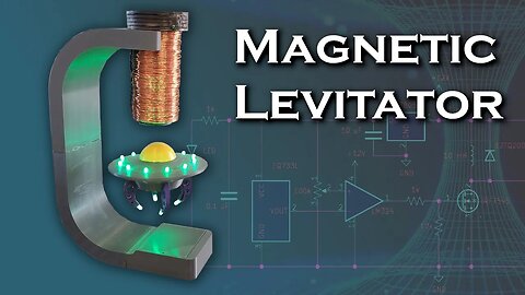
Large Magnetic Levitator
281221 Like and subscribe. This is an archive, check the link in the end if you are owner. Update 7/21/2022: STL files for the levitator have been uploaded
https://www.thingiverse.com/thing:5438518
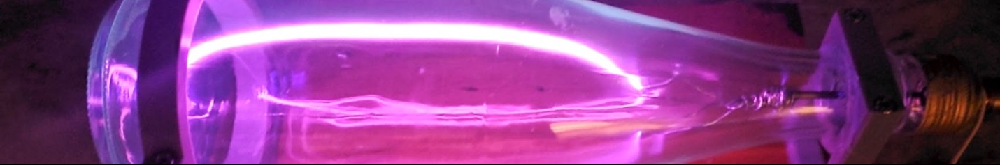
In this video I'm going to show how to build a attractive-type
("hanging") magnetic levitator. This is the easiest type of
levitator to build, because the electromagnet only operates with
one polarity, and only requires a single sensor and transistor
to operate. A repulsion-type levitator requires sensors for X
and Y position, and 4 coils with their own individual H-bridge
drivers.
The electromagnet is built from a 2" x 6" solid steel cylinder
as a core, and 600 turns of 16-gauge wire. The longest distance
I've managed to attract a large N52 magnet was about 9 inches
using 20 amps of current, but the coil heats up very fast with
that much current.
In this video, the magnets shown are hovering just outside the
region where the ferromagnetic attraction to the core would
overcome gravity, so the levitator takes very little power.
Levitating a 3-lb steel wrench only consumed ~5W, and a 30mm N52
magnet by itself consumes about 1W levitating a distance of
about 2" below the electromagnet.
The limiting factor in the levitation distance is the resolution
of the hall-effect sensor, which has an output of 20 mV/mT. Once
a 30mm N52 magnet goes beyond ~2 inches from the sensor, the
output is too small to be distinguished against the idle voltage
of the sensor. Changing to a more sensitive hall effect sensor
would increase the levitation range dramatically, but also
consume exponentially more power.
There is no microcontroller driving the electromagnet. The coil
is energized by a MOSFET that has its gate connected to the
output of an LM324 acting as a comparator. One input to the
LM324 is the hall effect sensor output, and the other input is a
reference voltage set by a potentiometer. I've found that it's
neccesary to make slight adjustments to the reference voltage
when changing to different magnets / loads on a particular
magnet.
Some of the key components used in this build:
-EQ733L Hall Effect Sensor
-LM324 Op-Amp
-IRF7545 MOSFET
-LM7805 5V linear regulator
-6.6 mF / 1 mH input filter
Some other figures:
-12-18V input voltage
-50-500 mA of current draw @ 12V depending on the load
-9.5 mH / 1.3 Ohm electromagnet (600 turns of 16 AWG)
-Magnets used in this video are 30x5 N52 magnets stacked
together and 2x 40x20 N52 magnets stacked together
Music used:
Serge Pavkin - Fractal
Serge Pavkin - Tech Research
Serge Pavkin - Intergalactic
Alexander Nakarada - Space Ambience
https://rumblevideoarchive.wordpress.com/
61
views
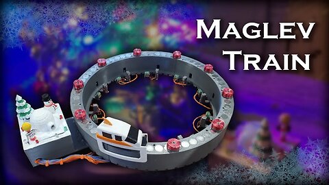
Building a Maglev train for my Christmas Tree
180422 Like and subscribe. This is an archive, check the link in the end if you are owner. In this video I'll show how i made a magnetic monorail train that uses infrared LEDs and phototransistors to trigger coils that accelerate it around a track. I built this because i wanted a train to go around my christmas tree and this seemed a lot more interesting than a regular toy train on rails.
The infrared tripwire that triggers the electromagnet coils is the same design i used for my second ball accelerator, which is described in detail in this video:
https://www.youtube.com/watch?v=uNbL3tRZeMQ
The train technically isn't a truly "levitating" train, because it straddles the rail, and its legs prevent the instability of magnetic repulsion from throwing it off to the left or right. A true maglev would have no physical contact with anything below or beside it. I'm working on a true levitating train for a future video, but it was too difficult to implement as a christmas decoartion.
IR LED / Phototransistor set:
https://www.amazon.com/Gikfun-Infrared-Emitter-Receiver-Arduino/dp/B01HGIQ8NG
Music Used:
Christmas Village - Aaron Kenny
Jolly Old St Nicholas (Instrumental) - E's Jammy Jams
Jingle Bells (Instrumental Jazz) - E's Jammy Jams
https://rumblevideoarchive.wordpress.com/
24
views
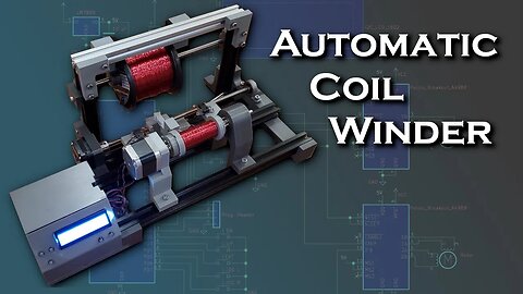
Automatic Coil Winding Machine
241121 Like and subscribe. This is an archive, check the link in the end if you are owner. Update 2/24/2022: I've uploaded the STL files for the machine. Note that not all of these parts are used in the final iteration and I didn't sort them yet
https://www.thingiverse.com/thing:5261994/files
Update 1/17/2022: Schematics and code are linked below. Currently I only have the values for 26 AWG in the code so you'll have to extrapolate for other wire gauges
https://drive.google.com/file/d/16xQJ93vJ1Sos_FNN_Kw97RhwrQ_QuLfG/view?usp=sharing
https://drive.google.com/file/d/1ZFmob1WSLG9xLbMRCjPKKMHWxX1yLvsC/view?usp=sharing
In this video I'll show how i made a machine to automate the process of coil winding. It can be used for electromagnets, tesla coils, loopstick antennas, transformers, generator coils or indcutive chokes - all things I use a lot of.
Code, Schematics, STLs:
I'm still making a few tweaks. Check back in a few days and I'll update this field with links to all of these.
Hardware:
-3A / 12V Wall wart with 5.5mm barrel jack
-A4988 Stepper Motor Drivers
-NEMA17 Stepper Motors
-3d printer leadscrew (8mm pitch?)
-20mm V-slotted rail
-M5 screws + T-nuts for railing
-M3 screws for motor mounts / set screws
-16x2 LCD with I2C bus driver
-LM7805 For logic supply
-ATMega328P-PU as the brain
Music:
Kevin MacLeod - George Street Shuffle
Serge Pavkin - Tech Research
Serge Pavkin - Futuristic Documentary
https://rumblevideoarchive.wordpress.com/
32
views
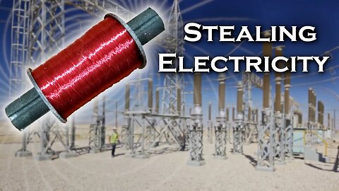
Stealing Electricity (The safe way)
260622 Like and subscribe. This is an archive, check the link in the end if you are. In this video i build a coil that's effectively a huge loopstick antenna with tuning capacitors to resonate at 60 Hz, which is mains frequency in North America. The coil can generate over 5 volts near running appliances or power cables, and charge a capacitor or light up some LEDs. It works by collecting the small magnetic flux leakage that every AC device produces.
The power generated is less than 100 μW in most cases, so it can't do anything very exciting, but it's really interesting to stand under a power line and see a capacitor charge from its leak. The biggest limiting factor seems to be that transmission lines which have opposite phases very close to each other result in a near-zero magnetic field at a distance from canceling out most of each others magnetic flux.
Some figures:
Coil Wire Gauge: 28 AWG
Number of turns: ~12,000
Coil Inductance: 28.1 H
Capacitor Value: 250 nF
Parts:
Coil Core: https://www.amazon.com/CynKen-35x200mm-Ferrite-Loopstick-Antenna/dp/B07PDG87V8
3 lb 28 AWG Magnet Wire:
https://www.amazon.com/BNTECHGO-AWG-Magnet-Wire-Transformers/dp/B07H4FQ8RS?th=1
Music:
Kevin MacLeod - George Street Shuffle
Kevin MacLeod - Groove Groove
https://rumblevideoarchive.wordpress.com/
35
views
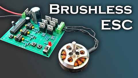
Brushless DC Speed Controller
010722 Like and subscribe. This is an archive, check the link in the end if you are. In this video I'm going to show how i built a brushless DC (BLDC) ESC (electronic speed controller) based on an Atmega328P microcontroller. This ESC was a prototype for a much larger one that I'll be using to drive the 1500-watt motors on my submarine. The video also explains the theory behind how a brushless DC motor works, and some troubleshooting tips that you may find helpful if you build one of these yourself.
The code i used for the first test can be found here:
https://simple-circuit.com/arduino-brushless-dc-motor-controller/
I later modified it to add a reverse function and adjusted the startup sequence settings to get a smoother start to my motors.
A guide on using the Atmega328P microcontroller by itself (without the arduino board) can be found here:
https://www.arduino.cc/en/Tutorial/BuiltInExamples/ArduinoToBreadboard
Hardware used:
MOSFETs: IRLZ44
Flyback Diodes: MUR120G
MOSFET Drivers: IR2101
5V Linear Regulator: LM7805
MOSFET Driver supply regulator: LM317
The motor used in the first part of this video is a very old brushless motor i used to fly on a drone, and I'm not sure what the part number is or if it's still in production.
The submarine motors are Turnigy SK3 6374-192 kV brushless motors. I've replaced their ball bearings with bronze sleeves, and coated the rotor and stator with enamel to protect against saltwater.
Arduino Code:
https://drive.google.com/file/d/1R6ROvEKI6wiVP7WfA2kJ13AO4JUQrIZ_/view?usp=sharing
https://rumblevideoarchive.wordpress.com/
65
views

8-Bit Adder built from 152 Transistors
250722 Like and subscribe. This is an archive, check the link in the end if you are. NOTE: The schematics incorrectly show the NPN transistors in reverse, with collector / emitter swapped.
This is my first attempt at doing a semi-serious project using digital logic. To really gain a good appreciation for the technology involved, i designed and built the circuit entirely out of discrete transistors instead of using pre-made IC's with logic gates (such as 74-series chips).
This adder is built entirely out of 2N3904 NPN transistors, 220k resistors for inputs, and 47k resistors for output pull-ups. There are a total of 152 transistors and 224 resistors, not including the LED resistors on the manual switch board. The first board in the stack uses an LM7805 and 10 uF capacitor to provide voltage regulation.
Because of the presence of a carry output bit on the 8th stage, this can technically output a 9 bit number. The A and B inputs are a single byte (8-bit value), so their maximum is 255, and the output can compute up to 510.
In the future I'm going to add a lot more features to this machine, like multiple RAM addresses than I can read/write to, a clock + ripple counter to increment the input bits automatically, and maybe even a binary-BCD converter which I could then use as an input to a 7-figure number display, which would give this computer a graphic output. I also want to add a reader for a 3d-printed punch card that will provide program instructions or data.
Music:
Kevin MacLeod - Groove Groove
Heatley Bros. - Dimension Drift
Prod Riddiman - Lost Time
Kevin MacLeod - George Street Shuffle
https://rumblevideoarchive.wordpress.com/
15
views
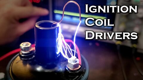
Ignition Coil Drivers
040722 Like and subscribe. This is an archive, check the link in the end if you are. In this video I show the differences between an ignition coil (pulse transformer) and other types of transformers, and a few different ways to drive them to get a high voltage output.
An ignition coil is an induction coil that has a relatively high primary inductance, but low turns ratio. It generates high voltage by building up a large magnetic field in its primary, and then suddenly collapsing it when current is shut off. The sudden collapse causes a voltage spike in the primary, which is stepped up even further in the secondary coil. These devices can easily produce 30,000 - 40,000 volts with a 12 volt input, and a modest turns ratio of between 15-20.
In the video i show how to drive one with a relay, single MOSFET, inductively coupled MOSFET half bridge, and a 600V IGBT, which was by far the most powerful and effective circuit.
Some important components:
-555 Timer
-LM7805 Linear Regulator
-IRF640 200V / 18A MOSFET
-12TQ200 200V / 15A Diode
-MUR120G 200V / 1A Diode
-STGP20H60DF 600V / 20A IGBT (Best results by far)
-1N4148 Diodes for duty cycle adjustment
Ignition coil used:
https://www.amazon.com/gp/product/B00809W952/ref=ppx_yo_dt_b_search_asin_title?ie=UTF8&psc=1
Music:
Serge Pavkin - Modern Technology
Kevin MacLeod - George Street Shuffle
Heatley Bros. - Otherworld
Serge Pavkin - Intergalactic
https://rumblevideoarchive.wordpress.com/
16
views
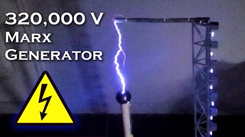
320,000 Volt Marx Generator
220921 Like and subscribe. This is an archive, check the link in the end if you are. This is my first attempt at building a high voltage impulse generator, better known as
a "Marx" generator, after its inventor, Erwin Marx. This is similar to a capacitor-diode voltage multiplier, but produces the voltage multiplication in brief pulses rather than continuously.
The circuit has 16 stages, each consisting of a 1 nF 20,000V capacitor, with 880k resistors on both the high and low side. Each 880k resistor actually consists of 4 220k resistors in series. This was done to divide the voltage across the resistors to prevent high voltage from
jumping over the resistor from one lead to the other.
The High Voltage DC source for the input to the generator is the same as i used in my voltage multiplier video, which provides more detail on the design:
https://www.youtube.com/watch?v=SmjKbNoK6nU&t=9s
The biggest arcs i managed to produce were 9.5" (24 cm) long at 320,000 volts. In theory, 320,000 volts should only cross ~4" (10~11 cm), because the breakdown voltage of air at 1 atmosphere is ~3MV/m. However, because of the sharp point on the positive electrode, a concentration of electrical charge forms which increases the effective voltage across
the terminals. Because of that, actual breakdown voltage ends up being 1~2 MV/m depending on electrode geometry
The arcs are long, but not particularly powerful. At 20KV, each 1nF capacitor only stores 0.2 Joules of energy, so an arc at full charge would contain no more than 3.2 Joules of energy.
Parts of interest:
20 KV / 1 nF caps:
https://www.amazon.com/Voltage-Ceramic-Capacitor-0-001uF-1000pF/dp/B07K6PH4SR/ref=sr_1_3?dchild=1&keywords=20kv+capacitor&qid=1632244619&sr=8-3
20 KV / 100 mA Diodes:
https://www.amazon.com/2CL2FM-100mA-Voltage-Diode-Rectifier/dp/B074S8JT96/ref=sr_1_6?dchild=1&keywords=20kv+diode&qid=1632244647&sr=8-6
Flyback Transformer Core(s):
https://www.amazon.com/5pairs-UY1658-Transformer-ferrite-Material/dp/B0146OG8VK/ref=sr_1_3?dchild=1&keywords=flyback+transformer+core&qid=1632244665&sr=8-3
Music:
Serge Pavkin - Digital Future
Serve Pavkin - Fundamental Analysis
Serge Pavkin - Modern Technology
https://rumblevideoarchive.wordpress.com/
27
views

DIY Remote Controlled Electric Lawnmower
260322 Like and subscribe. This is an archive, check the link in the end if you are. This is a rebuild of an RC lawnmower i built several years ago,
but using an electric mower this time. It pretty much operates
the same way an RC car / battlebot type vehicle does with just
two opposable motors and casters for front wheels.
In the future I plan to outfit the mower with FPV so that i can
drive it from inside the house, and possibly do automation even
further down the road.
Here's a list of my hardware:
- (2x) 35 A-h 12V lead acid batteries
- 275-Amp battery disconnect switch
https://www.amazon.com/gp/product/B07T288VN8/ref=ppx_yo_dt_b_asin_title_o01_s00?ie=UTF8&psc=1
- Turnigy 9x 2.4 GHz transmitter / reciever (100 mW tx power, i think)
- Sabertooth 2x32 dual brushed ESC (32 Amp / 33.6V max.)
https://www.dimensionengineering.com/products/sabertooth2x32
- 1" x 1" x 1/16" thick square tubing, welded with 0.030" flux cored wire
- (2x) 80mm 12V fans
Music:
Kevin MacLeod - George Street Shuffle
Heatley Bros. - Dimension Drift
Heatley Bros. - Sunset Beach
https://rumblevideoarchive.wordpress.com/
65
views
120,000-Volt Multiplier
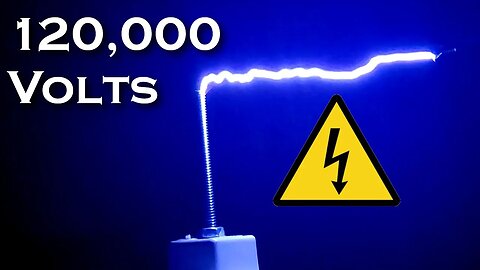
260622 Like and subscribe. This is an archive, check the link in the end if you are. This video shows how to build a cockroft-walton type voltage multiplier using a flyback transformer as a first stage driven by a ZVS driver with a 12V input. This circuit outputs 120,000 volts DC and arcs from ~4" away. Within about 2 feet of the device, you can feel the ion wind, and your hair being pulled toward it by electrostatic induction.
I didn't use any current limiting resistors, so the discharges are very dramatic but also extremely hard on the capacitors in the multiplier. After about 4-5 seconds of continuous discharge, there's little to no output, and the device needs a minute or two to recover before it can be used again. My guess being that the caps are swelling under such a high load.
The flyback and ZVS driver are both homemade. The circuit for the ZVS driver is explained in more detail in my video on induction heating :
https://www.youtube.com/watch?v=G9mudqJ46xM&t=2s
Parts List:
-1nF / 20kV Capacitors:
https://www.amazon.com/gp/product/B07V3XMHHL/ref=ppx_yo_dt_b_asin_image_o01_s00?ie=UTF8&psc=1
-20 kV / 100 mA Diodes:
https://www.amazon.com/gp/product/B07MVX689B/ref=ppx_yo_dt_b_asin_image_o05_s00?ie=UTF8&psc=1
-Ferrite U-cores for flybacks:
https://www.amazon.com/gp/product/B0146OG8VK/ref=ppx_yo_dt_b_search_asin_image?ie=UTF8&psc=1
-32 AWG magnet wire for secondary windings
-IRLZ44 MOSFETs with heatsinks for ZVS driver
-1N4148 Diodes for gate pull-downs
Music:
Serge Pavkin - Fractal
Serge Pavkin - Network
Serge Pavkin - Unknown
https://rumblevideoarchive.wordpress.com/
47
views

150V Mini Mortar
160221 Like and subscribe. This is an archive, check the link in the end if you are. In this video i make a tiny electromagnetic mortar powered from a 110V outlet. The coil consists of 150 turns of 24-gauge wire encapsulated in ferrous material to increase efficiency.
The capacitor bank is 1.45 mF @ 155V, carrying a total of 17.4 J of energy in the form of static electricity. An 8.1 gram steel ball reaches a maximum height of 12 ft, so i estimate an efficiency of 1.7%.
Music:
Prod. Riddiman - Lost Time
https://www.youtube.com/watch?v=5xUVDz5ha5U
Heatley Bros - Luminaire
https://www.youtube.com/watch?v=-c0EVoYGJRY
https://rumblevideoarchive.wordpress.com/
19
views

Electromagnetic Accelerator Improvements Part II
250722 Like and subscribe. This is an archive, check the link in the end if you are. Update 9/5/2021 - STL Files in link below:
https://drive.google.com/file/d/150P90fzySc2uXoxUL0e2ZlGPpEaGcZzJ/view?usp=sharing
In this video I make a new version of my ring accelerator that's capable of propelling steel balls 15 times faster than my first design. This is the second part in a series about improving accelerator coils
Here's some technical specs:
Input voltage: 24V
Number of coils: 4
Wire Gauge: 24AWG
Coil Current: 13A
Coil ID: 1.1"
Coil OD: 1.4"
Coil Length: 0.5"
Coil turns: 200
The final outer diameter is ~2" due to the addition of steel wire to create a magnetic flux guide or "shell".
FET Type: IRLZ44N
On time: ~8 ms at max. speed
Energy input per pulse: 2.6J
Ball mass: 65 grams
Ball kinetic energy: ~0.52J
Part I:
https://www.youtube.com/watch?v=OIw1JiMGHlw
Previous Accelerator design:
https://www.youtube.com/watch?v=qfmv-rHK_RU&t=2s
Music:
Serge Pavkin - Fractal
https://www.youtube.com/watch?v=8CFs1bVmCAg
Serge Pavkin - Tech
https://www.youtube.com/watch?v=cNnYlaF183I
Serge Pavkin - Unknown
https://rumblevideoarchive.wordpress.com/
10
views
Solid State Tesla Coil (SSTC) Part 1
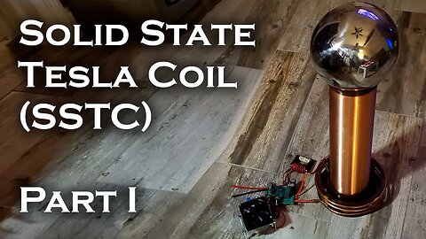
110721 Like and subscribe. This is an archive, check the link in the end if you are. This is the first part in series where I'm going to try to build a solid state tesla coil (SSTC) without any prior experience in doing so.
In this video i start off driving a tesla coil with a ZVS oscillator circuit connected to the primary, which doesn't work very well because there's no ability to adjust the frequency (aside from sliding a contact along the primary coil) and driving at resonance is unstable because the ZVS circuit will want to "drift off" when it sees the huge load that occurs at resonance.
The second, somewhat more successful circuit used a 555 timer to drive a single MOSFET on/off to oscillate the primary at resonance. This allowed me to dial in the resonant frequency with trimmer knobs, but it was easy to overshoot it, and i killed several MOSFETs in the process.
The FET I'm using for all these videos is an IRF250, and the videos shown are mostly with 12V of input, although in some of the clips there's 30V in. I use a PNP-NPN pair as a push-pull driver for the gate, but since these aren't moving more than about 200 mA, i think the gate isn't being driven hard enough, which is causing huge switching losses.
In the next video, I'm going to cover the proper procedure for tuning a tesla coil with an oscilloscope, driving the primary coil using feedback signals from the secondary coil, and techniques to avoid obliterating my MOSFETs.
Music Used:
Heatley Bros. - 8 Bit Go
Serge Pavkin - Fractal
Serge Pavkin - Tech
https://rumblevideoarchive.wordpress.com/
74
views

3d Printed Waterwheel Generator
240722 Like and subscribe. This is an archive, check the link in the end if you are. In this video I build a 12" 3d printed waterwheel and use it to generate electricity from a tiny amount of water flow. The parts are all printed from PLA. It uses a 10x gear ratio to drive a rotor with 99 neodymium fridge magnets on it and generate alternating current through 33 coils. I measured the maximum power output of a the generator at about 26 mW, and the whole thing is only ~9% efficient, so there's definitely room for improvement. I think I can achieve a larger gear-up ratio without adding much friction, which could dramatically increase the power output.
The shafts / bearings are 8mm, and i used 8mm x 3mm neodymium magnets for the generator rotor. The LED sets are wired antiparallel so they illuminate on opposite phases of the generator's AC output.
Since I live in a very flat place with no natural streams nearby, I got the water flow from a tiny aquarium pump which only moves a few LPM. The wheel runs at about 35 RPM in the sink and about 20 RPM on the pump.
STL Files:
https://www.thingiverse.com/thing:4889445
Music used in the video:
Kevin MacLeod - George Street Shuffle
Kevin MacLeod - Groove Groove
https://rumblevideoarchive.wordpress.com/
964
views
1
comment
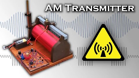
1 MHz AM Transmitter
040722 Like and subscribe. This is an archive, check the link in the end if you are. This video shows how to build a radio that transmits a simple 1 kHz tone on the AM band, which can be heard in a handheld radio or car radio up to 100 yards away. The radio uses an LC oscillator to drive a push-pull amplifier made from a 2N3906 and 2N3904 transistor. The audio tone is generated by a 555 timer. The radio can be powered by up to 40V, but in this video I'm only using 12V.
I experimented with transmitting on 1030 kHz then increased my frequency to 1620 kHz by changing the capacitors in the LC oscillator that generates the carrier wave. Because the frequency is so low in both cases, the antenna is nowhere near the wavelength, or even quarter wavelength. For antennas shorter than L/4, two major problems occur:
-The radiation resistance is extremely small (i.e. only a very small amount of the current in the antenna actually travels out as radio waves)
-The antenna acts as a capacitor and has huge impedance from capacitave reactance. In the video, i attempt to balance out the capacitave reactance with an adjustable inductor (or "loading coil"), with fairly good results.
The total power radiated was well below 1 mW in both cases. This is probably less power than something like a garage door opener transmits.
Note that radio transmissions in the US/Canada/Europe are regulated, and this device is only for demonstration. If you want to build a larger power transmitter, make sure you've got an amateur license and use one of the frequency bands allocated to amateurs.
Serge Pavkin - Business Infographics
Serge Pavkin - Commercial Agreement
Serge Pavkin - Fundamental Analysis
Heatley Bros. - Dimension Drift
Kevin MacLeod - George Street Shuffle
https://rumblevideoarchive.wordpress.com/
15
views
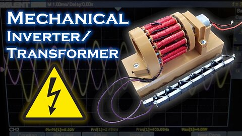
Mechanical inverter/transformer - 3V to 700V
230521 Like and subscribe. This is an archive, check the link in the end if you are. This video shows how I built a mechanical inverter/transformer, which can take 3V DC from a pair of AA Batteries and turn it into 700V. A long time ago before I knew how to build a solid state inverter circuit, I was curious about building a device like this as an alternative to generate AC from DC. It isn't really practical, but it's a really interesting toy to build/play with.
I use 16 6mm x 4mm neodymium magnets for the rotor with alternating N-S-N-S polarity and 16 coils made from #6 screws wound with about 1,300 turns of 32 gauge magnet wire. The rotor is driven by a 3V motor that turns at about 2,800 RPM.
The multiplier circuit uses 100 nF film capacitors with 1N4006 diodes.
Music:
Heatley Bros - Otherworld
https://www.youtube.com/watch?v=1GYItux32P4
Heatley Bros - 8 bit chillout
https://www.youtube.com/watch?v=8El8ZP8LMFE
https://rumblevideoarchive.wordpress.com/
12
views
Wireless Power RC Car
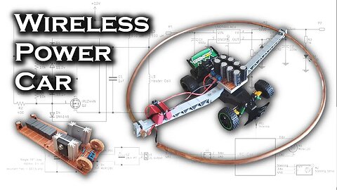
160521 Like and subscribe. This is an archive, check the link in the end if you are. This is an upgraded version of the wireless power transmitter from my previous video being used to power a small 3.6-volt RC car. The transmitter/receiver resonate at 100 kHz, and a bridge rectifier on the RC car feeds a DC-DC buck converter that steps the voltage down to 3.6V. The car pulls around 1 amp, so the transmitter has no problem powering it as long as it's inside the loop or within about 1 ft outside the edge.
The transmitter runs at 31V and consumes 3-4 amps depending on the load.
Harware used:
RC Car:
https://www.amazon.com/dp/B07X7MRG3F?psc=1&ref=ppx_yo2_dt_b_product_details
DC-DC Buck Converter (3.0-40V in / 1.5-35V out):
https://www.amazon.com/dp/B06XZ1DKF2?psc=1&ref=ppx_yo2_dt_b_product_details
Transmitter / ZVS Driver:
-2x IRF250 Mosfets
-2x MUR120G Diodes
-2x 13V Zener Diodes
-2x 120 uH 5A inductors
-20x 47 nF 400VAC capacitors rated at 14 mOhm ESR
-2x Copper lugs from Home Depot
-1/4" Copper tubing
Receiver / Rectifier:
-2x 1uF 600V Capacitor
-1/4" Copper tubing (~16" diameter)
-8x 35V 3300 uF Capacitors
-4x MUR120G Diodes
3d printed parts are made from ordinary PLA and modeled in CATIA
Induction heater video (explains ZVS driver schematic / how to build):
https://www.youtube.com/watch?v=G9mudqJ46xM&t=44s
Music Used:
Heatley Bros. - 8 bit chillout
https://www.youtube.com/watch?v=8El8ZP8LMFE
Heatley Bros. - 8 bit emperor's club
https://www.youtube.com/watch?v=jy-ZMc2csbE
https://rumblevideoarchive.wordpress.com/
26
views
Wireless Power Transmission
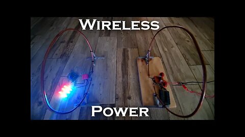
020521 Like and subscribe. This is an archive, check the link in the end if you are. Here i'm going to show how i built a wireless power transmitter / receiver that can power things up to ~2 ft away. The Tx/Rx "coils" are actually single 15" loops of 1/4" copper tubing. The transmitter and receiver are in resonance (just like a Tesla coil), so the maximum amount of power can be transferred. I'm only putting about 40-45 watts of power into my transmitter, so I was very surprised by the results i got.
Technical Specs:
Loop Inductance: 1.05 uH
Resonant Cap value: 3 uF
Resonant Frequency: 89.7 kHz
MOSFET: IRF640 (200V VDS, 1.5V VGS threshold). This FET has a very high R_DS of about 0.2 ohm so they get very warm and they also go into latch-up easily because of the low gate threshold voltage. I don't reccommend this part, and in future builds I'll be replacing this with an IRF250 or IRF260.
Gate Diodes (Also used on rx rectifier): MUR120 (200V / 75 nS recovery time)
LED Board resistors: 330 ohm
Magnet in the electromagnet part of the video is a 40mm x 20mm N52
In the future I plan to make a dramatically larger ZVS driver that can handle around 1,000 watts and power a 4-6 ft transmitter coil to fly a
small drone several feet off the ground, which will be carrying a reciever coil instead of a battery. This type of device is also really useful for transferring power through a barrier, or to a rotating object.
Music used:
Serge Pavkin - Fractal
Serge Pavkin - Tech
Serge Pavkin - Network
https://www.youtube.com/c/SergePavkinMusic
https://rumblevideoarchive.wordpress.com/
36
views

My Homemade Submarine
080123 Like and subscribe. This is an archive, check the link in the end if you are. This is a video about my homemade submarine, which I've been working on off and on for the last 2 years. I'm planning to make some videos with it in the coming weeks, so I thought it would be a good idea to do an introductory video about how i designed/built it.
It's a "semi-wet ambient" type submarine, meaning the pressure inside is the same as the outside water pressure, and the cabin is partially flooded. The pilot and passenger sit in a bubble of trapped air underwater that's equivalent to pushing a cup upside down in your sink, similar to a diving bell.
Power for propulsion, pumps, and lights is provided by a pair of 12V / 100AH lead acid batteries, which are sealed off against water entry, and have their terminals potted in rubber to prevent corrosion (in future videos, the batteries will be series-connected for 24V). Pneumatics for cabin air and buoyancy control come from a pair of 120 Cubic ft steel air tanks pressurized to 4,000 psi. I have an adapter that allows me to connect regular hardware store NPT fittings to the diving regulators on the tanks.
Motors are 12V/30A saltwater trolling motors made by newport that allow me to cruise at about ~3 knots surfaced and about 2 knots submerged. In future videos, I'll be running Turnigy 6374 brushless outrunners specially modified for underwater use with 7.25x5 3 bladed props.
My hope is to eventually use this sub to explore reefs and shipwrecks along the Florida coast.
Music:
Serge Pavkin - Intergalactic
Serge Pavkin - Fractal
Heatley Bros. - Dimension Drift
Serge Pavkin - Universe
https://rumblevideoarchive.wordpress.com/
30
views