
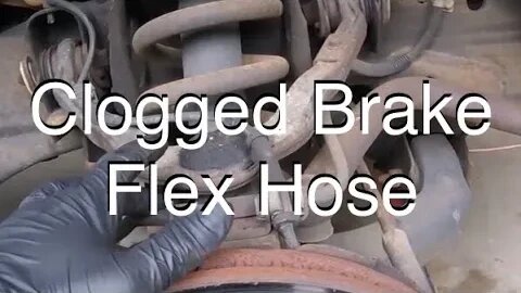
Locked Up Caliper By Clogged Brake Hose
In this video I show you a great example of a locked up brake caliper caused by a clogged brake hose. I also go into some techniques in diagnosing a clogged brake hose that causes a locked up caliper.
!!Warning!! If your brakes are locked up its going to be very hot just after driving. The whole area that is affected is going to be very hot. Let the vehicle cool down before attempting to diagnose the problem. Don't touch a hot rotor or any hot brake component! Injury can occur. An infrared thermometer would be suggested to verify that the area is cool enough to work on.
Note: this video and the videos linked below are very superficial and in no way should take the place of an appropriate repair manual for the vehicle which you are working on.
Here is a link to the video on diagnosing a locked up caliper:
https://youtu.be/1Mor9N9Rv2w
Here is a link on how to bleed brakes using the "buddy system":
https://youtu.be/6DeuMPgQDrE
Of course it goes without saying but I'll say it. Tighten your brake bleeder and brake line where it goes into the flex hose back up after testing. Bleed as needed. I soft brake pedal is a good indication that the brakes need to be bleed.
Disclaimer:
Barbour's Auto Help is not responsible for any damage or personal injury incurred in the process of performing any auto repairs done by you the viewer. Auto repair and diagnostics are very dangerous.
Repair and diagnose your vehicle at your own risk. It is the viewers responsibility to verify all information and procedures as outlined in YOUR REPAIR MANUAL AND OWNERS MANUAL FOR YOUR VEHICLE. Owning and using a repair manual suited for your vehicle is essential for correctly and safely performing ANY repair to your vehicle. Always wear safety glasses and heed all instructions for use applicable to any piece of equipment you may use. Also, I make no guarantee that the information given in this video is completely accurate for all situations and applications. I also make no guarantee that you will make a proper diagnosis for your problem by using this video. Use the information found in this video at your own risk.
13
views
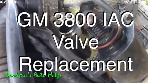
How to replace an IAC valve on a GM 3.8L V-6 series 2
In this video I'll be showing you how to replace an IAC valve on a GM 3.8L V-6 series 2. IAC stands for "idle air control". This device is responsible for regulating the idle of your engine and performs the dashpot function for the throttle. Some symptoms for a faulty IAC valve or motor are and engine that stalls out at idle, an engine that has an irregular or high idle.
Note: It is very rare that this will have to be done but, "before installing a new IAC valve, measure the distance that the valve is extended. The measurement should be made from the motor housing to the end of the valve cone (pintle). The distance should be no greater than 1 1 / 8 inch (28mm). If the pintle is extended too far, adjustment is required, otherwise damage may occur when the IAC valve is installed. Adjust the IAC valve by compressing the pintle to achieve the correct length."-- Info provided by a fellow youtuber Buckets Of Rust. I did some digging and found this to be good information.
The process for replacement is very simple. I hope the video helps.
Also, if your new valve does not come with a new o-ring you may be able to reuse the old o-ring. Inspect the o-ring for damage. If o-ring is damaged replace it. This is the orange o-ring that was shown on the end of the valve when the valve was removed.
!!!!WARNING!!!!
Repair your vehicle at your own risk. While this channel will always strive to give you the most accurate information regarding automotive repair it would be foolish to assume that by watching a 5-30 minute video you too will be able to repair your vehicle without any errors or risk to your safety or risk to others safety. Costly mistakes can and will happen. When performing automotive repairs there is a high risk of personal injury. There is also a high risk for EXTREME frustration. There is also a risk of damaging your vehicle. This channel assumes no responsibility or liability for any personal injury or property damage that may take place using the information found in this channels videos. It is absolutely imperative that you the viewer, and performer of said repairs, receive as much education concerning automotive repair and particularly the repair you are considering performing. While the videos featured on this channel do go into detail about particular repairs this channel does not claim that the information provided in said videos are 100% complete and accurate. YOU MUST HAVE A REPUTABLE REPAIR MANUAL FOR THE VEHICLE THAT YOU PLAN TO WORK ON THAT CONTAINS THE INFORMATION YOU NEED TO PROPERLY REPAIR SAID VEHICLE. Follow all repair procedures as outlined in your repair manual. Compare the information in your manual with the information in this channels videos. Follow your repair manual over this channels videos. Follow all safety instructions and warnings found in your manual. Also, read and follow the instructions for any piece of equipment, chemical, or tool that you may use in any repair. Also, check out the owners manual for the vehicle you are working on. There is a lot of good, important, and helpful information that can be found in it. Finally, above all, do everything you can to keep yourself safe. WEAR SAFETY GLASSES. WEAR IMPERMIABLE GLOVES. UNDERSTAND THE CHEMICALS YOU WILL BE EXPOSED TO AND GUARD YOURSELF FROM THEM.
Note: Even the most educated, seasoned, and talented technicians, or mechanics, are still subject to personal injury and property damage while performing automotive repair. I say again, use the information found in this channels videos at your own risk. Repair your vehicle at your own risk.
Music by:
Zombie Rock by Audionautix is licensed under a Creative Commons Attribution license (https://creativecommons.org/licenses/by/4.0/)
Artist: http://audionautix.com/
Created with MAGIX Movie Edit Pro 2016
17
views
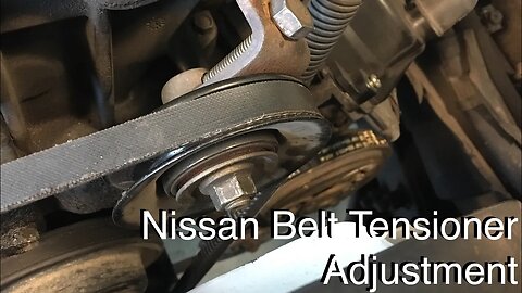
Nissan Belt Tensioner Adjustment
In this video I'll show you how to loosen and tighten a Nissan accessory drive belt tensioner. The particular belt tensioner shown in the video is used on a myriad of Nissans over the coarse of many years. I don't have a list of all the years and models that this tensioner is used on. However, if your tensioner looks like the one shown in this video then this video will probably be of help to you. WARNING! DO VERIFY THIS PROCEDURE IN YOUR REPAIR MANUAL JUST TO BE SURE THAT THIS INFORMATION IS APPLICABLE TO YOUR VEHICLE OR THE VEHICLE YOU ARE WORKING ON. (Be sure the engine is not running when performing this procedure.)
DISCLAIMER
Barbour's Auto Help is not responsible for any damage or personal injury incurred in the process of performing any auto repairs done by you the viewer. Automotive repair is extremely dangerous. Repair your vehicle at your own risk. It is the viewers responsibility to verify all information and procedures as outlined in YOUR REPAIR MANUAL AND OWNERS MANUAL FOR YOUR VEHICLE. Owning and using a repair manual suited for your vehicle is essential for correctly and safely performing ANY repair to your vehicle. Always wear safety glasses and heed all instructions for use applicable to any piece of equipment you may use. Due to circumstances out of the control of Barbours Auto Help, Barbours Auto Help makes no guaranty that by the use of the information given in this video a quality repair will be made. Barbour'sAutoHelp makes no guaranty that the information provided is totally complete, syncronized and accurate. Verify everything using an appropriate repair manual. Follow the repair manual over this videos content. You can do it. Do it right and do it safely.
Repair your vehicle at your own risk! Barbour's auto help does not guaranty a proper repair using these techniques.
7
views
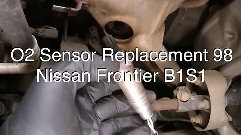
98 Nissan Frontier Bank 1 Sensor 1 O2 Sensor Replacement
In this video I'll take you through the steps to replace an oxygen sensor on a 1998 Nissan Frontier 2.4L.
Note: Be sure to let the vehicle cool for several hours, with the engine off, before attempting this. Exhaust temperatures can be very high and you could burn yourself severely if you do not let the exhaust system cool properly.
Please verify all procedures shown in this video with a reputable repair manual. Reference your repair manual for torque specifications. The use of a torque wrench was not shown in the video when the oxygen sensor was installed. Using a torque wrench to tighten the sensor down is required to properly torque the sensor.
DISCLAIMER
Barbour's Auto Help is not responsible for any damage or personal injury incurred in the process of performing any auto repairs done by you the viewer. Automotive repair is extremely dangerous. Repair your vehicle at your own risk. It is the viewers responsibility to verify all information and procedures as outlined in YOUR REPAIR MANUAL AND OWNERS MANUAL FOR YOUR VEHICLE. Owning and using a repair manual suited for your vehicle is essential for correctly and safely performing ANY repair to your vehicle. Always wear safety glasses and heed all instructions for use applicable to any piece of equipment you may use. Due to circumstances out of the control of Barbours Auto Help, Barbours Auto Help makes no guaranty that by the use of the information given in this video a quality repair will be made. Barbour'sAutoHelp makes no guaranty that the information provided is totally complete, syncronized and accurate. Verify everything using an appropriate repair manual. Follow the repair manual over this videos content. You can do it. Do it right and do it safely.
Repair your vehicle at your own risk! Barbour's auto help does not guaranty a proper repair using these techniques.
5
views
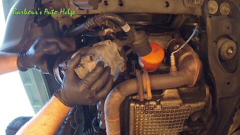
Compressor Replacement 01 Ford Escape 3.0L
In this video I'll go over some basic steps in replacing an A/C compressor on an 01 Ford Escape 3.0L V-6. This is a relatively simple process and usually takes around 1 hour to do.
Note: as mentioned on the video the a/c system will have to be evacuated in order to service the compressor. You must be certified to handle refrigerant to evacuate the a/c system. (see EPA laws for handling R134a). You also will need special equipment in order to evacuate and recharge the system.
Also, note: While this video does go into some detail in the process for replacing the a/c compressor I do not claim that the process shown in the video is as would be outlined in a reputable repair manual. I always recommend using a reputable repair manual for making repairs to any vehicle. I also do not guarantee that our a/c compressor will be installed correctly by using this video as a repair guide. USE A MANUAL to verify everything shown in this video to insure that you in fact are doing things correctly. The information given in this video is pulled from my experience in doing a/c work over the years and some things shown are generic.
As mentioned at about the 6 minute mark if your old a/c compressor failed and blew trash throughout the system then a system flush will be needed including replacing the receiver dryer or accumulator, the orifice tube or the thermostatic expansion valve, and possibly certain lines depending on weather an a/c flush machine is capable of flushing those lines. An a/c flush machine is not the same machine used for evacuating and recharging the a/c system. This is a machine that uses a solvent to internally clean a/c parts. In order remove the debris deposited in the a/c system by the faulty compressor either flushing components or replacing components will be needed. As mentioned earlier, the receiver dryer or accumulator, the orifice tube or thermostatic expansion valve and possibly certain lines will have to be replaced. These parts cannot be flushed and require replacement. Refer to the operating manual of the flush equipment used for more information about what can and cannot be flushed.
Also, after installing the a/c compressor you will need to have the system vacuumed and then recharged with the correct amount of refrigerant. I would suggest a 45 minute vacuum before recharging.
DISCLAIMER
Barbour's Auto Help is not responsible for any damage or personal injury incurred in the process of performing any auto repairs done by you the viewer. Automotive repair is extremely dangerous. Repair your vehicle at your own risk. It is the viewers responsibility to verify all information and procedures as outlined in YOUR REPAIR MANUAL AND OWNERS MANUAL FOR YOUR VEHICLE. Owning and using a repair manual suited for your vehicle is essential for correctly and safely performing ANY repair to your vehicle. Always wear safety glasses and heed all instructions for use applicable to any piece of equipment you may use. Due to circumstances out of the control of Barbours Auto Help, Barbours Auto Help makes no guaranty that by the use of the information given in this video a quality repair will be made. Barbour'sAutoHelp makes no guaranty that the information provided is totally complete, syncronized and accurate. Verify everything using an appropriate repair manual. Follow the repair manual over this videos content. You can do it. Do it right and do it safely.
Repair your vehicle at your own risk! Barbour's auto help does not guaranty a proper repair using these techniques.
15
views
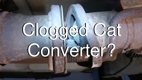
How I Figured Out Exhaust Restriction (Clogged Catalytic Converter)
In this video I'll show you how I figured out that this 2001 Ford Escape 3.0L had an exhaust restriction or a clogged catalytic converter. I started by connecting a vacuum gauge to the intake manifold and measured the vacuum present when the vehicle was at idle. Usually a normally running engine will have somewhere around 18"-22"hg of vacuum at idle. I had around 12"hg at idle. I also revved the engine and held the throttle at around half throttle. When I did this the vacuum immediately went down to 0 and stayed there. On a normally operating engine the vacuum would go down initially when opening the throttle but is would quickly go back up. As mentioned the vacuum stayed at 0 when the throttle was held. So, I knew I had a restricted exhaust. The next step was to find out where the restriction was. I suspected a common restriction just because of the very poor performance of the engine. But, for grins and giggles I checked the cat converters by removing the O2 sensors and inspecting them with a bore scope. I did not see anything obvious so the next thing I did was run the engine with the bank 2 sensor 2 oxygen sensor taken out. Both the front head and the rear head are joined together by a "Y" pipe so removing this O2 sensor would alleviate any back pressure for both heads. (Note: You have to be very careful when doing this as you can damage your vehicle by exposing parts to the extreme temperatures of the exhaust gas that will come out of any O2 sensor port. You could even catch the vehicle on fire. If your O2 sensor port is in an enclosed area and exhaust cannot be safely vented from said exhaust port without damaging close by parts or catching the vehicle on fire then It would be my suggestion to NOT DO IT! Try finding the restriction by some other means such as taking sections of the exhaust of and inspecting sections internally with a bore scope.
USE THE METHOD OF RUNNING THE VEHICLE WITHOUT AN O2 SENSOR IN AT YOUR OWN RISK!! YOU CAN DAMAGE YOUR VEHICLE AND START A FIRE!! Also Note: I had to remove a splash shield so that it would not become damaged) Back to my story.... So I ran the vehicle without this O2 sensor in and it ran very well. So, I had a restriction in the exhaust that was common to both banks of the engine. Back cat, the cat converter after the two front cats, was suspect. Conveniently the back cat has a flange just in the front of it. I disconnected this flange and there it was. Cat converter material from the front cats had clogged the exhaust at this location. New converters and cleaning the material from exhaust was needed. And that's it in a nut shell.
Note: keep a fire extinguisher near by in case of fire.
Now, this video just shows how I discovered that the exhaust was clogged on this particular vehicle in this particular way. Though I show some diagnostic techniques this video is not comprehensive when It comes to showing you how to properly diagnose your vehicle. The video has very good information but it is not comprehensive. I would suggest using a repair manual.
Also, as a rule of thumb, I would suggest waiting at least an hour before handling exhaust and exhaust components after the vehicle is ran. If you don't you could end up with a very serious burn.
Also, It is good to note that there is usually a root cause of the exhaust becoming restricted. So, further diagnosis may be needed.
DISCLAIMER
Barbour's Auto Help is not responsible for any damage or personal injury incurred in the process of performing any auto repairs done by you the viewer. Automotive repair is extremely dangerous. Repair your vehicle at your own risk. It is the viewers responsibility to verify all information and procedures as outlined in YOUR REPAIR MANUAL AND OWNERS MANUAL FOR YOUR VEHICLE. Owning and using a repair manual suited for your vehicle is essential for correctly and safely performing ANY repair to your vehicle. Always wear safety glasses and heed all instructions for use applicable to any piece of equipment you may use. Due to circumstances out of the control of Barbours Auto Help, Barbours Auto Help makes no guarantee that by the use of the information given in this video a quality repair will be made. Barbour'sAutoHelp makes no guarantee that the information provided is totally complete, syncronized and accurate. Verify everything using an appropriate repair manual. Follow the repair manual over this videos content. You can do it. Do it right and do it safely.
Repair your vehicle at your own risk! Barbour's auto help does not guaranty a proper repair using these techniques.
60
views
1
comment
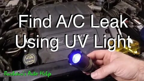
Find Refrigerant Leaks With a UV light
In this video I go over the use of a UV light to find refrigerant leaks in an A/C system. UV lights are so useful when it comes to finding A/C leaks. Being able to see the dye glowing where the leak really helps in giving you confidence when diagnosing a problem with an A/C system.
Do Note: This video did not show me inspecting every component of the A/C system from all angles. You will have to inspect every component by shining the UV light at all angles while wearing the "special glasses" that usually come with a dye light kit. What I mean is that just shining the light at the front or the top of the A/C compressor is not good enough. The leak may be located underneath or on the back side of the compressor, so you have to inspect it from all those angles as you could miss locating the leak. This goes for the other components of the A/C system too. Take your time and inspect your system thoroughly.
If your A/C system is not equipped with refrigerant dye it can be added. Of coarse this video is not designed to go into details about this. Consult a repair manual for more information. (Warning! This may not apply to all vehicles)
As for the evaporator core. Obviously this component cannot be directly inspected as it is inside the HVAC case behind the instrument panel. So shine your UV light on the drain port of the evaporator core and look for evidence of dye. An electronic leak detector may be needed for this in some cases and also in some cases the evaporator core can be assumed to be leaking if leaks are not found elsewhere in the system. (you take gamble on that one though because you may have overlooked some other component that is leaking)
Also Note: A very common source of refrigerant leaks are the A/C service ports. Sometimes taking a little pag oil (or whatever oil your a/c requires) and poring it into the service port can reveal a leak. This is usually indicated by bubbles coming up through the oil inside the port that is now filled with oil.
Disclaimer:
Children do not attempt this! Also, this video is very superficial in nature and is not designed to make anyone an expert at finding leaks on an A/C system using a dye light. There may be some cases where only experience can help you determine where a leak is. Its not always obvious. I make no guarantee that you can and will diagnose your A/C leak properly using the information found in this video. Always wear safety glasses when working around vehicles. Also, do not attempt to discharge refrigerant.... Its illegal and can potentially injure you or kill you in some cases. Always work in a well ventilated area. Do some research. Get to know more about your vehicle before attempting to work on it.
GENERAL DISCLAIMER
Barbour's Auto Help is not responsible for any damage or personal injury incurred in the process of performing any auto repairs done by you the viewer. Automotive repair is extremely dangerous. Repair your vehicle at your own risk. It is the viewers responsibility to verify all information and procedures as outlined in YOUR REPAIR MANUAL AND OWNERS MANUAL FOR YOUR VEHICLE. Owning and using a repair manual suited for your vehicle is essential for correctly and safely performing ANY repair to your vehicle. Always wear safety glasses and heed all instructions for use applicable to any piece of equipment you may use. Due to circumstances out of the control of Barbours Auto Help, Barbours Auto Help makes no guaranty that by the use of the information given in this video a quality repair will be made. Barbour'sAutoHelp makes no guaranty that the information provided is totally complete, syncronized and accurate. Verify everything using an appropriate repair manual. Do it right and do it safely.
Repair your vehicle at your own risk! Barbour's auto help does not guaranty a proper repair using these techniques.
11
views

Headlamp Bulb Replacement 05 Honda Odyssey
In this video I'll show you how to replace a low beam headlamp bulb on an 05 Honda Odyssey.
Take care not to touch the glass of the bulb as this could cause premature failure of the bulb.
DISCLAIMER
Barbour's Auto Help is not responsible for any damage or personal injury incurred in the process of performing any auto repairs done by you the viewer. Automotive repair is extremely dangerous. Repair your vehicle at your own risk. It is the viewers responsibility to verify all information and procedures as outlined in YOUR REPAIR MANUAL AND OWNERS MANUAL FOR YOUR VEHICLE. Owning and using a repair manual suited for your vehicle is essential for correctly and safely performing ANY repair to your vehicle. Always wear safety glasses and heed all instructions for use applicable to any piece of equipment you may use. Due to circumstances out of the control of Barbours Auto Help, Barbours Auto Help makes no guaranty that by the use of the information given in this video a quality repair will be made. Barbour'sAutoHelp makes no guaranty that the information provided is totally complete, syncronized and accurate. Verify everything using an appropriate repair manual. You can do it. Do it right and do it safely.
Repair your vehicle at your own risk! Barbour's auto help does not guaranty a proper repair using these techniques.
3
views
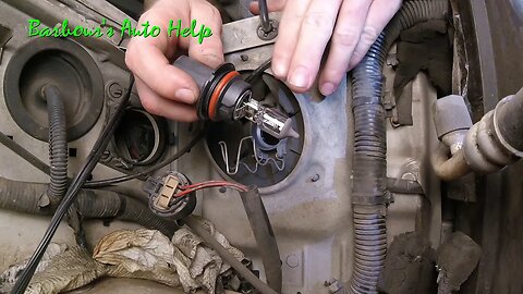
Headlamp Bulb Replacement 1998 Nissan Frontier
In this video I'll show you how to replace a headlamp bulb on a 1998 Nissan Frontier 2.4L. The side replaced is the drivers side in the video. The passenger side is similar, however, removing the battery may make it a bit easier on you. The battery removal is not explained in this video. Please refer to your repair manual for this information.
DISCLAIMER
Barbour's Auto Help is not responsible for any damage or personal injury incurred in the process of performing any auto repairs done by you the viewer. Automotive repair is extremely dangerous. Repair your vehicle at your own risk. It is the viewers responsibility to verify all information and procedures as outlined in YOUR REPAIR MANUAL AND OWNERS MANUAL FOR YOUR VEHICLE. Owning and using a repair manual suited for your vehicle is essential for correctly and safely performing ANY repair to your vehicle. Always wear safety glasses and heed all instructions for use applicable to any piece of equipment you may use. Due to circumstances out of the control of Barbours Auto Help, Barbours Auto Help makes no guaranty that by the use of the information given in this video a quality repair will be made. Barbour'sAutoHelp makes no guaranty that the information provided is totally complete, syncronized and accurate. Verify everything using an appropriate repair manual. You can do it. Do it right and do it safely.
Repair your vehicle at your own risk! Barbour's auto help does not guaranty a proper repair using these techniques.
12
views
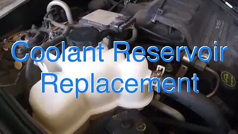
Coolant Reservoir Replacement 01 Ford Escape 3.0L
In this video I'll be showing how to replace a coolant reservoir on an 01 Ford Escape 3.0L.
Note: The system will need to be filled and bled properly before returning the vehicle to service. Failure to do so could result in an over heat condition which could damage your engine and cooling system. The fill and bled procedure is not shown in this video. Please use an reputable repair manual for information pertaining to this procedure.
Note: The red handled pliers used in the video are actually made for clamping off hoses. It is not recommended to use anything other than "hose clamp off pliers" to clamp off your hoses. Using anything other than hose clamp off pliers could damage your hoses. Note: Read and understand the instructions given by the manufacturer of any tool you have and only use the tool as intended by the manufacturer.
Here is a link to a video showing how to vacuum fill a cooling system:
https://youtu.be/1beZZCBUnt0
DISCLAIMER
Barbour's Auto Help is not responsible for any damage or personal injury incurred in the process of performing any auto repairs done by you the viewer. Automotive repair is extremely dangerous. Repair your vehicle at your own risk. It is the viewers responsibility to verify all information and procedures as outlined in YOUR REPAIR MANUAL AND OWNERS MANUAL FOR YOUR VEHICLE. Owning and using a repair manual suited for your vehicle is essential for correctly and safely performing ANY repair to your vehicle. Always wear safety glasses and heed all instructions for use applicable to any piece of equipment you may use. Due to circumstances out of the control of Barbours Auto Help, Barbours Auto Help makes no guaranty that by the use of the information given in this video a quality repair will be made. Barbour'sAutoHelp makes no guaranty that the information provided is totally complete, syncronized and accurate. Verify everything using an appropriate repair manual. You can do it. Do it right and do it safely.
Repair your vehicle at your own risk! Barbour's auto help does not guaranty a proper repair using these techniques.
7
views
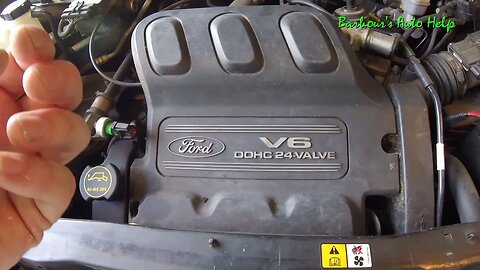
Firing Order and Cylinder Identification 01 Ford Escape 3.0L
In this video I'll go over the firing order and cylinder identification for an 01 Ford Escape 3.0L.
Cylinder 1-3 are on the rear cylinder head starting with cylinder #1 closest to the accessory drive followed by cylinder #2 and then #3 as you move closer to the transmission. Cylinders 4-6 can be found on the front cylinder staring with cylinder #4 closest to the accessory drive followed by cylinder #5 and #6 as you move toward the transmission.
Knowing the cylinder identification and location is important especially when trying to diagnose a trouble code that is specific to a particular cylinder. Examples of cylinder specific codes are misfire codes, ignition coil codes, and injector codes.
DISCLAIMER
Barbour's Auto Help is not responsible for any damage or personal injury incurred in the process of performing any auto repairs done by you the viewer. Automotive repair is extremely dangerous. Repair your vehicle at your own risk. It is the viewers responsibility to verify all information and procedures as outlined in YOUR REPAIR MANUAL AND OWNERS MANUAL FOR YOUR VEHICLE. Owning and using a repair manual suited for your vehicle is essential for correctly and safely performing ANY repair to your vehicle. Always wear safety glasses and heed all instructions for use applicable to any piece of equipment you may use. Due to circumstances out of the control of Barbours Auto Help, Barbours Auto Help makes no guaranty that by the use of the information given in this video a quality repair will be made. Barbour'sAutoHelp makes no guaranty that the information provided is totally complete, syncronized and accurate. Verify everything using an appropriate repair manual. You can do it. Do it right and do it safely.
Repair your vehicle at your own risk! Barbour's auto help does not guaranty a proper repair using these techniques.
112
views
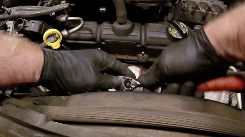
Spark Plug and Ignition Wire Replacement 08 Chrysler Town & Country 3.8L
In this video I'll demonstrate how to replace spark plugs and ignition wires on a 2008 Chrysler Town and Country 3.8L. This is a relatively simple task and should not be too difficult to do. In the video you'll notice that I do not show removal and replacement of all spark plugs and ignition wires. I only change two spark plugs, one in the front cylinder head and one in the rear cylinder head. I also, only show the installation of one ignition wire. The other ignition wires are installed in a similar manner and should be routed similarly. As mentioned at the beginning of the video the ignition coil is numbered on the top of each tower or electrode. Rout each ignition wire according to the number shown on each coil tower. For example, if one end of the ignition wire is connected to the coil tower numbered 3 then the other end of the wire would connect to the spark plug on the number 3 cylinder. The other wires are installed and routed similarly. Of course there will be different length of ignition wires provided. Longer wires go the the cylinders closest to the accessory drive followed by the wires of medium length and then the shortest length as you get closer to the transaxle.
Warning!! Let the vehicle cool completely before attempting this. Let the vehicle sit for several hours, not running, before attempting this. Even then use caution as the exhaust and engine could still be hot.... Don't burn yourself.
DISCLAIMER
Barbour's Auto Help is not responsible for any damage or personal injury incurred in the process of performing any auto repairs done by you the viewer. Automotive repair is extremely dangerous. Repair your vehicle at your own risk. It is the viewers responsibility to verify all information and procedures as outlined in YOUR REPAIR MANUAL AND OWNERS MANUAL FOR YOUR VEHICLE. Owning and using a repair manual suited for your vehicle is essential for correctly and safely performing ANY repair to your vehicle. Always wear safety glasses and heed all instructions for use applicable to any piece of equipment you may use. Due to circumstances out of the control of Barbours Auto Help, Barbours Auto Help makes no guaranty that by the use of the information given in this video a quality repair will be made. Barbour'sAutoHelp makes no guaranty that the information provided is totally complete, syncronized and accurate. Verify everything using an appropriate repair manual. You can do it. Do it right and do it safely.
Repair your vehicle at your own risk! Barbour's auto help does not guaranty a proper repair using these techniques.
20
views
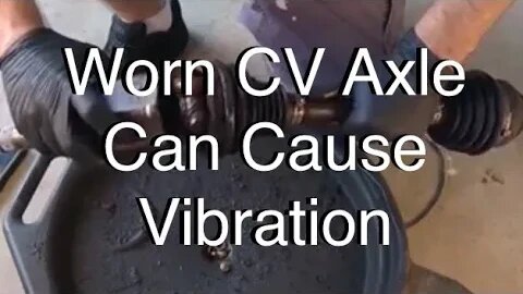
How a Worn CV Axle Can Cause Vibration
This video is mainly an informational video. In this video I have a great example of a CV axle with a worn inner joint that caused a vibration upon acceleration. I take the inner joint apart and show what happened to the inner joint and explain how a worn inner CV axle joint can cause a vibration upon acceleration.
Note: While it is very common for a worn inner CV axle joint to cause a vibration upon acceleration you need to keep in mind that this is not the only thing that can cause this symptom. You will need to properly diagnose your vehicle before performing a repair. Below is a link to a video that will give you SOME information to help you in diagnosing a vibration upon acceleration. (while this video has great information, it may not have ALL the information you need to properly diagnose your vehicle.)
Here is the link to that video: https://youtu.be/OyXtBqExkec
Also, the explanation of how an electric motor can slow a vehicle down was just a superficial explanation. Of coarse it was not the purpose of the video to go into depth about that. Also at about the 1:00 mark I mention that the electric motor slows the vehicle but I did it in a way that may seem like I said the motor uses the brake rotors to slow the vehicle down. What I was trying to say is that the motor, not the brakes, slow the vehicle.
DISCLAIMER
Barbour's Auto Help is not responsible for any damage or personal injury incurred in the process of performing any auto repairs done by you the viewer. Automotive repair is extremely dangerous. Repair your vehicle at your own risk. It is the viewers responsibility to verify all information and procedures as outlined in YOUR REPAIR MANUAL AND OWNERS MANUAL FOR YOUR VEHICLE. Owning and using a repair manual suited for your vehicle is essential for correctly and safely performing ANY repair to your vehicle. Always wear safety glasses and heed all instructions for use applicable to any piece of equipment you may use. Due to circumstances out of the control of Barbours Auto Help, Barbours Auto Help makes no guarantee that by the use of the information given in this video a quality repair will be made. Barbour'sAutoHelp makes no guarantee that the information provided is totally complete, syncronized and accurate. Verify everything using an appropriate repair manual. Follow the repair manual over this videos content. You can do it. Do it right and do it safely.
12
views
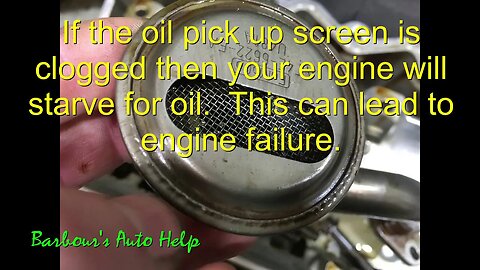
Good Reason to Change Your Oil
In this video I give you a great visual of what can happen to the inside of your engine if the oil is not changed on a regular basis. The engine shown at the beginning of the video has some serious sludge build up. This sludge can really clog things up including the oil pick up screen. In severe cases the oil pick up screen can become so clogged that it does not allow for proper oil flow through the engine and could result in engine damage. Toward the end of the video I show the insides of an engine that has been properly maintained. The difference is astounding. The metal is nice and shiny and there is no build up of sludge whatsoever. Be sure to change the oil in you engine in accordance with the manufacturer of your vehicle. It could save you from having to buy a new engine.
2
views
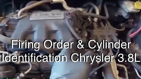
Firing Order & Cylinder Identification 08 Chrysler Town and Country 3.8L V-6
In this video I'll go over the cylinder identification and firing order on an 08 Chrysler Town and Country 3.8L. The odd numbered cylinders are on the rear cylinder head, or the right cylinder head, and they are 1/3/5 from the front of the engine where the serpentine belt is to the back of the engine where the transmission is. The evenly numbered cylinders are on the front cylinder head, or the left cylinder head, and they are 2/4/6 front the serpentine belt to the transmission. The firing order is 1-2-3-4-5-6.
If you forget the cylinder identification you can always just look at the coil pack. The coil pack has numbers on the top of it where each of the ignition wires connect to the coil pack. The number represent the cylinder that the coil fires where the ignition wire connects to it. For example, if you find the #2 next to where a wire plugs into the coil pack then that is the wire that fires cylinder #2. So if you where to follow that wire to the spark plug then the cylinder that that spark plug fires would be cylinder #2. Same principle for the other cylinders. (This is assuming that the wires are installed correctly)
DISCLAIMER
Barbour's Auto Help is not responsible for any damage or personal injury incurred in the process of performing any auto repairs done by you the viewer. Automotive repair is extremely dangerous. Repair your vehicle at your own risk. It is the viewers responsibility to verify all information and procedures as outlined in YOUR REPAIR MANUAL AND OWNERS MANUAL FOR YOUR VEHICLE. Owning and using a repair manual suited for the vehicle you are working on is essential for correctly and safely performing ANY repair to said vehicle. Always wear safety glasses and heed all instructions for use applicable to any piece of equipment you may use. Due to circumstances out of the control of Barbours Auto Help, Barbours Auto Help makes no guaranty that by the use of the information given in this video a quality repair will be made. Barbour'sAutoHelp makes no guaranty that the information provided is totally complete, syncronized and accurate. Verify everything using an appropriate repair manual. Follow the repair manual over this video's content. You can do it. Do it right and do it safely.
Repair your vehicle at your own risk! Barbour's auto help does not guaranty a proper repair using these techniques.
39
views
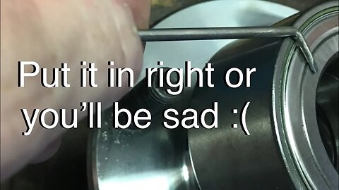
Correct Installation/ Orientation of a Press in Wheel Bearing With an Integrated Magnetic Reluctor
In this video I'll share information that will hopefully prevent you from installing a wheel bearing, that has an integrated magnetic reluctor, backwards. Many vehicles today use wheel bearing that use these magnetic tone rings or reluctors instead of the older tone rings that look like gears. The principle is the same as the older tone rings. as the wheel spins the sensor senses the rate of rotation of the wheel. However, If the hub bearing is put in backwards this integrated magnetic reluctor, or tone ring, will not trigger the abs sensor for that wheel and a code will be set in the ABS module. The ABS light will come on and the ABS system will be shut down.
Slowing down and taking a little additional time to determine which side of the wheel bearing has the reluctor or tone ring built in to it will help you in installing the hub bearing in correctly. It will also save you money as if the bearing was installed incorrectly it will have to be destroyed in order to replace it. Yes, you will have to buy another wheel bearing because they are not going to take a damaged part back. (unless you have a buddy working at the parts house). So, be careful and take your time.
Note: this video is just meant to inform you that this bearing can be installed incorrectly and how to determine which side of the wheel bearing has the magnetic reluctor or tone ring built into it so that you know which side the wheel speed sensor needs to next to when the bearing is installed. This video is not a complete tutorial of how to install a press in wheel bearing. THIS VIDEO MAY NOT APPLY TO EVERY VEHICLE OUT THERE THAT HAS THIS DESIGN WHEEL BEARING. YOU NEED A REPAIR MANUAL TO CONFIRM IF THIS INFORMATION IS APPLICABLE TO THE VEHICLE YOU ARE WORKING ON.
Here are some other videos pertaining to integrated magnetic reluctors. Its my suggestion to watch as many videos and learn as much as you can about this before replacing the wheel bearing.
This video shows how a special tool can allow you to see the tone ring: https://youtu.be/e32t-d32SEg
And another showing this same test but without the added information: https://youtu.be/B6pGrqPiqhY
This video gives a good visual of how the sensor is positioned in relation to the magnetic reluctor. (I don't necessarily agree with the guys diagnosis but its a good visual): https://youtu.be/Hp69uQ7oLns
DISCLAIMER
Barbour's Auto Help is not responsible for any damage or personal injury incurred in the process of performing any auto repairs done by you the viewer. Automotive repair is extremely dangerous. Repair your vehicle at your own risk. It is the viewers responsibility to verify all information and procedures as outlined in YOUR REPAIR MANUAL AND OWNERS MANUAL FOR YOUR VEHICLE. Owning and using a repair manual suited for your vehicle is essential for correctly and safely performing ANY repair to your vehicle. Always wear safety glasses and heed all instructions for use applicable to any piece of equipment you may use. Due to circumstances out of the control of Barbours Auto Help, Barbours Auto Help makes no guaranty that by the use of the information given in this video a quality repair will be made. Barbour'sAutoHelp makes no guaranty that the information provided is totally complete, syncronized and accurate. Verify everything using an appropriate repair manual. Follow the repair manual over this videos content. You can do it. Do it right and do it safely.
28
views
Heater Control Valve Location 05 Honda Odyssey 3.5L
This video will show where the heater control valve is located on an 05 Honda Odyssey 3.5L. The location may be the same or similar for all generation 3 Honda Odysses..... Knowing where the part is is sometimes half the battle.
2
views
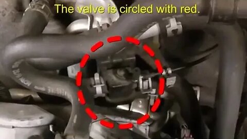
Heater Control Valve Cable Fix 05 Honda Odyssey 3.5L
In this video I'll show you how to prevent the heater control valve cable from popping off the heater control valve on an 05 Honda Odyssey 3.5L. The idea for this video was brought about by a question one of my viewers had about his A/C not blowing cold in the full cold setting. After doing a little digging I found that this is a common problem with some Odysseys, well at least the 05 to my knowledge. The fix is very simple and involves taking a little vacuum hose and applying it to the valve to keep the cable from popping off. This is probably one of the cheapest and easiest repairs anyone could make on a vehicle and it works. So, if you are having a problem with your A/C not blowing as cold in the full cold position or the heater not blowing hot in the full hot position then I'd advise you to take a look at this component and make sure the cable is connected. If it's not then follow the instructions in the video to repair.
The heater control valve is located on the fire wall just behind the engine by the way.
Here is a link showing how to replace a driver side blend door actuator.
https://youtu.be/IuekQMwy3sw
Here is a link to a video showing how to repair a drivers side blend door actuator.
https://youtu.be/jWcWUlbksco
Warning!! Please use extreme caution when working around your vehicle's cooling system. Yes, your heater control valve is a part of that system. Be sure the vehicle is totally cool before working on it and even then uses extreme caution because the cooling system could still be hot.
DISCLAIMER
Barbour's Auto Help is not responsible for any damage or personal injury incurred in the process of performing any auto repairs done by you the viewer. Automotive repair is extremely dangerous. Repair your vehicle at your own risk. It is the viewers responsibility to verify all information and procedures as outlined in YOUR REPAIR MANUAL AND OWNERS MANUAL FOR YOUR VEHICLE. Owning and using a repair manual suited for your vehicle is essential for correctly and safely performing ANY repair to your vehicle. Always wear safety glasses and heed all instructions for use applicable to any piece of equipment you may use. Due to circumstances out of the control of Barbours Auto Help, Barbours Auto Help makes no guaranty that by the use of the information given in this video a quality repair will be made. Barbour'sAutoHelp makes no guaranty that the information provided is totally complete, syncronized and accurate. Verify everything using an appropriate repair manual. Follow the repair manual over this videos content. You can do it. Do it right and do it safely.
12
views
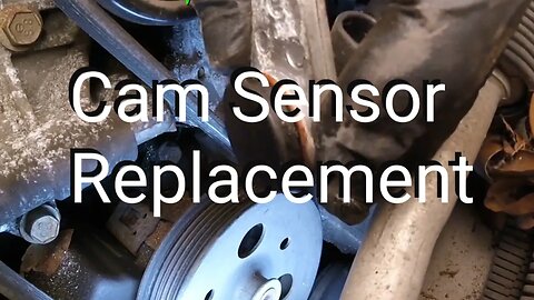
Camshaft Position Sensor Replacement GM 3.8L Series 2
In this video I'll demonstrate how to replace a camshaft position sensor on a GM 3.8L series 2 V-6. The vehicle featured in this video is a 2001 Pontiac Bonneville. Please verify in your repair manual if this procedure is the same for the GM 3.8L series 2 V-6 you are working on. There may be a few out there that the removal and replacement procedure may be different. Verify that the procedure shown in the video is the same for your vehicle.
Do note: If your vehicle has a diagnostic trouble code or codes pertaining to the camshaft position sensor it will be necessary to erase these codes after the repair. The codes can be erased by disconnecting the negative battery cable from the battery for 10 minutes. (Of coarse if you followed the directions given in the video you would have already disconnected the negative battery cable before beginning the replacement procedure and the codes should be erased by the time the sensor is replaced and the negative cable is reconnected.)
As mentioned in the video, it is recommended to disconnect the negative battery cable before replacing the sensor. ***BE SURE YOU HAVE YOUR RADIO CODE BEFORE DISCONNECTING YOUR BATTERY CABLE*** (the code should be in your glove compartment in your owners manual or information packet) The radio may not work if this code is not entered into the radio after the battery has been disconnected. Locate the code and be sure you have it before going forward with repairs.
Of course, you will need to reconnect the negative battery cable end after the sensor is replaced. (I'm sure you would have figured that out) :)
Also: Its not a bad idea to rotate the engine and verify the trigger or magnet is not missing from the cam sprocket. On some vehicles the trigger or magnet can fall out. You'll need a mirror and a flash light to verify this. Repair as needed. This video does not go into this as it is not the purpose of the video.
DISCLAIMER
Barbour's Auto Help is not responsible for any damage or personal injury incurred in the process of performing any auto repairs done by you the viewer. Automotive repair is extremely dangerous. Repair your vehicle at your own risk. It is the viewers responsibility to verify all information and procedures as outlined in YOUR REPAIR MANUAL AND OWNERS MANUAL FOR YOUR VEHICLE. Owning and using a repair manual suited for the vehicle you are working on is essential for correctly and safely performing ANY repair to said vehicle. Always wear safety glasses and heed all instructions for use applicable to any piece of equipment you may use. Due to circumstances out of the control of Barbours Auto Help, Barbours Auto Help makes no guaranty that by the use of the information given in this video a quality repair will be made. Barbour'sAutoHelp makes no guaranty that the information provided is totally complete, syncronized and accurate. Verify everything using an appropriate repair manual. Follow the repair manual over this video's content. You can do it. Do it right and do it safely.
Repair your vehicle at your own risk! Barbour's auto help does not guaranty a proper repair using these techniques.
84
views
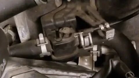
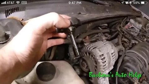
How to replace an EGR valve on a GM 3.8L V-6 series 2
In this video I'll be showing you how to replace an EGR valve on a GM 3.8L V-6 series 2. It's a very simple task but having a visual demonstration before getting into it ads a bit more confidence! Note the vehicle featured in the video is an 01 Pontiac Bonneville 3.8L. This procedure should be similar if not the same for most GM 3.8L Series 2 Engines. Verify this in your repair manual.
Warning!! Be sure the engine is totally cool before performing this task.
Please note: Barbour's Auto Help makes no guarantee that by following the steps and information found in this video that you will make an accurate diagnosis or quality repair. This video is very superficial in nature and is only intended to assist you in diagnosing your vehicle.
!!!!WARNING!!!!
Repair your vehicle at your own risk. While this channel will always strive to give you the most accurate information regarding automotive repair it would be foolish to assume that by watching a 5-30 minute video you too will be able to repair your vehicle without any errors or risk to your safety or risk to others safety. Costly mistakes can and will happen. When performing automotive repairs there is a high risk of personal injury. There is also a high risk for EXTREME frustration. There is also a risk of damaging your vehicle. This channel assumes no responsibility or liability for any personal injury or property damage that may take place using the information found in this channels videos. It is absolutely imperative that you the viewer, and performer of said repairs, receive as much education concerning automotive repair and particularly the repair you are considering performing. While the videos featured on this channel do go into detail about particular repairs this channel does not claim that the information provided in said videos are 100% complete and accurate. YOU MUST HAVE A REPUTABLE REPAIR MANUAL FOR THE VEHICLE THAT YOU PLAN TO WORK ON THAT CONTAINS THE INFORMATION YOU NEED TO PROPERLY REPAIR SAID VEHICLE. Follow all repair procedures as outlined in your repair manual. Compare the information in your manual with the information in this channels videos. Follow your repair manual over this channels videos. Follow all safety instructions and warnings found in your manual. Also, read and follow the instructions for any piece of equipment, chemical, or tool that you may use in any repair. Also, check out the owners manual for the vehicle you are working on. There is a lot of good, important, and helpful information that can be found in it. Finally, above all, do everything you can to keep yourself safe. WEAR SAFETY GLASSES. WEAR IMPERMIABLE GLOVES. UNDERSTAND THE CHEMICALS YOU WILL BE EXPOSED TO AND GUARD YOURSELF FROM THEM.
Note: Even the most educated, seasoned, and talented technicians, or mechanics, are still subject to personal injury and property damage while performing automotive repair. I say again, use the information found in this channels videos at your own risk. Repair your vehicle at your own risk.
Music by:
Zombie Rock by Audionautix is licensed under a Creative Commons Attribution license (https://creativecommons.org/licenses/by/4.0/)
Artist: http://audionautix.com/
Created with MAGIX Movie Edit Pro 2016
12
views
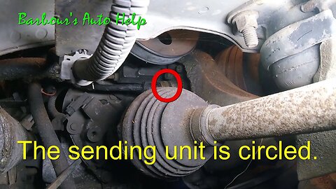
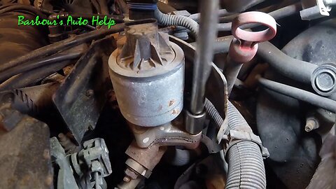
Oil Pressure Sending Unit Location GM 3.8L Series 2
In this video I go over the location of the oil pressure sending unit for a GM 3.8L Series 2 V-6. The particular vehicle featured in this vehicle is a 2001 Pontiac Bonneville.
Note: To the best of my memory the location of this sending unit should be the same for all GM 3.8L Series 2 engines. I've worked on many of these throughout the years and do not recall a different location. That being said, I'm using my memory and experience .
Do verify in you repair manual the location of this sensor. I am not sure if this location is applicable to the super charged engines.
The sending unit is located on the right rear of the engine just below the power steering pump and just above the inner joint of the passenger side CV axle. The oil filter is just below it.
Here is a link to the video showing how to replace this sensor.
https://youtu.be/Gj2eno8SkCg
2
views
How To Check and Adjust Power Steering Fluid GM 3.8L Series 2
In this video I show how to check and adjust the power steering fluid level on an 01 Pontiac Bonneville 3.8L Series 2. This procedure is probably similar if not the same for all vehicles equipped with the GM 3.8L Series 2 V-6. (Always verify videos relevance in your repair manual).
The "dip stick" which is a part of the cap has 2 level marks. One mark is the "full cold" and the other mark is the "full hot". The fluid level should be adjusted to the appropriate level depending on the temperature of the fluid. If the fluid is hot and the vehicle has been ran for a while then the goal would be to fill the fluid to the level indicated by "hot" on the dip stick. If the fluid is cold and the vehicle has been sitting over night then the goal would be to fill the fluid to the level on the dip stick indicated by "full cold".
Note: It is my suggestion that the fluid level should be checked and adjusted while the vehicle is cold. (after sitting for several hours with the engine not running). WARNING! The location of the fluid reservoir and cap is hard to get to and is next to heater hoses, which get very hot when the vehicle has been running and could potentially burn you.
Use only power steering fluid that is compatible with your vehicle. Consult a parts pro for correct fluid.
DISCLAIMER
Barbour's Auto Help is not responsible for any damage or personal injury incurred in the process of performing any auto repairs done by you the viewer. Automotive repair is extremely dangerous. Repair your vehicle at your own risk. It is the viewers responsibility to verify all information and procedures as outlined in YOUR REPAIR MANUAL AND OWNERS MANUAL FOR YOUR VEHICLE. Owning and using a repair manual suited for your vehicle is essential for correctly and safely performing ANY repair to your vehicle. Always wear safety glasses and heed all instructions for use applicable to any piece of equipment you may use. Due to circumstances out of the control of Barbours Auto Help, Barbours Auto Help makes no guaranty that by the use of the information given in this video a quality repair will be made. Barbour'sAutoHelp makes no guaranty that the information provided is totally complete, syncronized and accurate. Verify everything using an appropriate repair manual. Follow the repair manual over this videos content. You can do it. Do it right and do it safely.
Repair your vehicle at your own risk! Barbour's auto help does not guaranty a proper repair using these techniques.
4
views
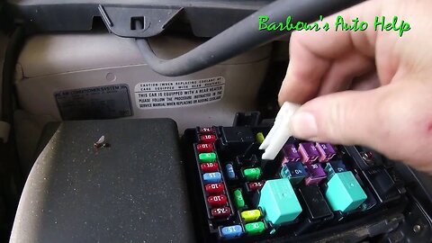
05 Honda Odyssey Under Hood Fuse Box Location
In this video I go over the under hood fuse box location on an 05 Honda Odyssey 3.5L. I also explain somethings about what you can find inside. u
2
views

Resealing my VVT Solenoid 05 Honda Odyssey 3.5L
In this video I take you along with me as I attempt to perform some "hack engineering" on my 2005 Honda Odyssey 3.5L. I suspected that my VVT solenoid, aka spool valve, had developed a leak between the two halves of the body. There is a seal inside that was not available aftermarket or dealer that tends to leak. The seal is available now. So, the "official repair" would be to replace seals or replace the whole VVT solenoid. (I would suggest replacing the seals as it is much cheaper. In this video I attempt to fix it another way.
Do note: This video is not intended to be used for the purposes of showing you how to repair your vehicle in the manner I did in the video. The method used in the video it not a "proper repair" and could potentially damage your engine. DON'T DO IT THIS WAY!
One way it could damage your engine is that it may not fix the leak at all and you could leak all your oil out causing severe engine damage. Another way it could damage your engine is by clogging up the small passages inside your engine with RTV. RTV could break away from the inside of the valve and travel into the engine where it could potentially dam up the flow of engine oil to important components of the engine causing failure of said components and or complete engine failure.
So, I say again, do not repair your vehicle in this manner. It could cost you hundreds if not thousands of dollars. This video is intended for gaining information about this problem and also for entertainment. (I may be sorry I did this to my own vehicle. Though I'm not terrible concerned about it as I can repair it for just the cost of parts)
Now that part number for the VVT solenoid is 918-078 (this is a Dorman VVT Solenoid and note this part # was provided as help to you and not for the purposes of promoting Dorman products.)
As for the aftermarket seals, which I would suggest replacing instead of replacing the whole valve. The part # is 917-0268-1. It's a VVT Solenoid Gasket Kit, it's one kit, but contains both gaskets.
Here is a link to a website that sells this part : https://www.napaonline.com/en/p/NDP91702681
Same thing on the NAPA parts as the Dorman parts. I'm no promoting either although I think they are both great!
Note: Always consult your parts pro to insure that any part you purchase is the correct part for your vehicle including the one mentioned above.
Sorry, I do not have the torque specifications for the three bolts that hold the two halves of the housing together and I do not know where to get that information. I would suggest using a repair manual when performing the task of replacing the seals. (Not sure if this information is available.)
Here is a link to a video showing how to Remove and Replace the VVT Solenoid: https://youtu.be/aKYR3-2NJ4A
Here is a link to a video showing other methods of cleaning mating surfaces on engines and engine parts.
https://youtu.be/Uy5p-cUge5s
10
views

05 Honda Odyssey EGR Valve Location
In this video I show where the EGR valve is located on a 05 Honda Odyssey 3.5L V-6.
4
views