Build your own switch mode voltage regulator for your Commodore VIC 20. Replace the obsolete LM323K.
To reduce the current in my Commodore VIC 20, I decided to change the LM323K linar regulator with an switchmode voltage regulator. I start a small project and create the schematic in KiCAD and order the PCB from JLCPCB. All the components are in surfacemount and it was easy to essably them by hand in my lab.
The switch-mode regulators are open hardware now! You can dowload the gerber files from Github:
https://github.com/DigitalArtDeco/SwitchModePSUinTO3
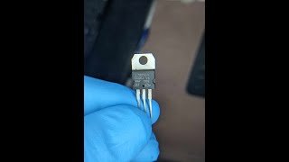
This is a switching voltage regulator for replace the obsolete LM323K. It is a synchronous buck (step-down) converter. It provides an output voltage of 5 V. The input voltage can be 4,5 to 24 Volts with a continuous current of 3 amps! At room temperature, it does not need a heatsink! The switching voltage regulator operates with a frequency of 500kHz. This device has the same shape as the original TO-3 package. The TO-3 package was used in old devices like game consoles, computers from the 1980 and pinball machines. Therefore you can use this switching voltage regulator to replace your old linear regulators and prevent from damage your old machines. Extremely low ripple and noise! The Pins and the surface of the device are gold plated. The design of the regulator was done with precise calculation and test in the lab. The pcb traces was done to meet the radiation and emission regulations!
Features:
Output Ripple (20MHz bandwidth) with 12V input and with a current of 0,5A: 15mV p-p !!
Wide input range from 4,5 - 24 Volts DC Fixed output voltage of 5 Volts DC
Efficiency up to 96%!
Voltage drop from no load to full load: less than 0,95 %
Low Profile
Short-circuit protection and thermal shutdown
Shielded Power Inductor
Music: By masterdrwho
-
 9:49
9:49
Retro with Pedro
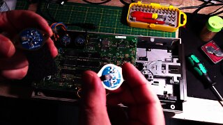
3 years ago $0.01 earnedRaplacing the voltage regulators in the Commodore VC 1541 disk drive.
79 -
 23:20
23:20
Diyelektronics
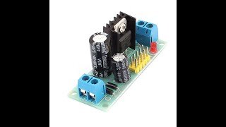
4 months ago $0.04 earnedLM7805 Voltage Regulator on a PCB! | DIY Electronics Tutorial
361 -
 12:04
12:04
Endless Money Pits
2 years agoAdjustable External Voltage Regulator Installation
18 -
 1:15
1:15
Larson Electronics - American Made and Manufactured Industrial Lighting and UVC Products
2 years agoProgrammable 6000W Single Output AC/DC Power Supply 180-264V AC Input to Single 24V DC Output
39 -
 3:30
3:30
TerryCoxese channel
1 year agoMore In The Description R-Tech JC-Tech DC12V 1A Ul-Listed Switching Power Supply Adapter for CC...
17 -
 17:03
17:03
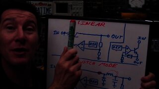
EEVblog Channel
14 years agoEEVblog #90 - Linear and LDO regulators and Switch Mode Power Supply Tutorial
6 -
 7:26
7:26
Diyelektronics
4 months agoUnlocking the Power: A Step-by-Step Guide to LM7805 Voltage Regulator
20 -
 19:15
19:15
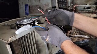
taddydigest
1 year agoHow to Replace Module and Motor with PSC Motor and relay? #psc #relay #hvac
37 -
 7:22
7:22
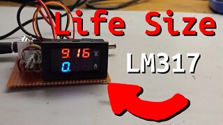
Sine Lab
1 year agoLife Size LM317! - How do linear regulators work?
1 -
 8:51
8:51
SeidelRanch
3 years agoTroubleshooting A RV Converter and Replacing A RV Converter | Inteli-Power 4500
275