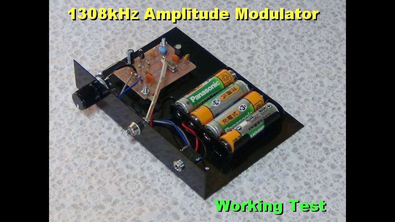
Simple 1308kHz Amplitude Modulator PCB Testing
4 years ago
34
This is a very simple 1308kHz Amplitude Modulator Board, to listen oldies with vintage tube radios that do not equip AUX input. One transistor C1815 and one crystal oscillator 1308kHz are on the board. Originally this PCB requires 3-5m antenna wire but in this test I removed, cause the receiver was very close. Power consumption is small, 20mA or around. The making up detail was published in my article, DENSHI KOSAKU MAGAZINE No.5 2009.
--- (c) 2021 Osamu Terao, Allrights reserved ---
Loading comments...
-
 4:46
4:46
terasyu2
4 years agoSimple Light Modulator and De-Modulator
16 -
 0:32
0:32
Electronic Investigation
4 years agoCNC aluminum with simple G code -early testing
1083 -
 2:43
2:43
SchoolReports
4 years agoTesting A 500cc Oxygen Absorber. Simple Science Experiment With Oxygen Absorbers.
1041 -
 15:19
15:19
Donald Feury
4 years ago $0.01 earnedI love how simple testing is in Go - Go / Golang Testing Tutorial
113 -
 8:18
8:18
joelpaiva
4 years agoSimple Cake Decoration
60 -
 18:03
18:03
Nikko Ortiz
48 minutes agoNikko Ortiz Night Routine...
1 -
 21:37
21:37
Forrest Galante
13 hours ago6 Deadly Sea Monsters That Actually Exist
96.4K4 -
 LIVE
LIVE
JdaDelete
1 hour agoElden Ring | First Playthrough Episode 10
97 watching -
 8:10
8:10
MattMorseTV
21 hours ago $55.65 earnedDemocrats caught COLLUDING with Epstein.
58.4K114 -
 LIVE
LIVE
Pepkilla
1 hour agoBreakfast First ~ Camo Grind Call Of Duty Black Ops 7
140 watching