T-meic inverter PV system Ground Fault Troubleshooting
Here are some basic troubleshooting steps for finding and fixing ground faults in the T-MEIC Inverter- PV system.
1. Ground fault occurs.
2. Inverter GFI system detects ground fault and shuts down individual inverter in Power Conversion System, PCS. Caution, other inverters and central transformer are still energized.
3. Inverter associated with ground fault should have solid red fault indicator light on, and should have stopped. Listen for "no noise" from inverter; as compared to other inverters in PCS.
4. Connect to PCS SCU, via PC interface, using ethernet connection. 192.168.20.100, for the PCS.
5. Log in to T-meic interface and go to home page for specific faulted inverter, 192.168.20.X, where X is inverter number. Inverter number in IP address is one more than actual identification number, because SCU home page takes first number. For example 192.168.20.2 is the IP for inverter 1. Take screenshot at the inverter home page.
6. Go to "maintenance mode" then go to "error event log page"; and take screenshot.
7. Go to "measurement" for voltage readings and choose faulted inverter page and take screenshot. There, you should see three inverter voltages: "Positive-to-Ground", "Negative-to-Ground", and “difference between Positive-to-Ground and Negative-to-Ground".
8. Allow for voltage to stabilize then take screenshot of voltage readings. For example, If string open circuit voltage, VOC, is 1200 volts; Un-faulted, normal, voltage readings should be about 600 Volts in "Positive-to-Ground", 600 Volts in "Negative-to-Ground", and 0 Volts in "difference between Positive-to-ground and Negative-to-Ground". Normal voltage readings may vary by up to 150 Volts, and inverter may remain un-faulted with such voltages.
9. Go to electrical drawings and identify which combiner boxes, CMBs, are associated with faulted inverter.
10. Tech 1 goes and opens, shut off, all associated CMBs.
11. Voltage should normalize, to 600 volts, 600 volts, 0 volts, plus or minus 150 Volts.
12. As tech 2 monitors voltage at SCU interface, tech 1 closes or turns CMBs back on; one by one.
13. Again, tech 2 monitors voltage at SCU to see when voltage returns to faulted conditions. When this happens, the faulted CMB has been identified.
14. To narrow the location of the ground fault to the individual string, you may disconnect all associated home runs, negatives and positives. Then check each voltage between Negative and Positive, between Negative to Ground, and between Positive to Ground. There should be full VOC between Negative and Positive, and close to 0 volts, or fast bleed down of ghost voltage, between Negative-to-Ground, and between Positive-to-Ground.
15. When you find higher voltages, over 50 Volts negative or positive, between Positive-to-Ground or Negative-to-Ground; that string is faulted. Remember, there should be normally close to 0 Volts between Positive-to-Ground, and between Negative-to-Ground. A fast “bleed-down” of voltage is ghost voltage, this is a normal reading. Abnormal voltages will be stable negative values, or very slow bleed down of values over 50 volts.
16. For the faulted string, you may narrow the fault location by noting the string VOC, in this case 1200 volts. Then noting voltage reading between Positive to Ground, and Negative to Ground. For example, if Positive to Ground is 400 volts, and the Negative-to-Ground is 800 volts; divide each of these voltages by the individual module VOC. In this case; 49.8 volts. So, the result are: 8 modules between Positive to Ground, and 16 modules between Negative-to-Ground. So, the fault should be located 8 modules from start of string, or 16 modules from end of string.
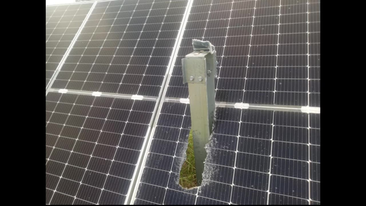
17. Faults can be melted connectors, broken modules, chaffed wiring, or water intrusion in modules. Module damage can be hairline cracks, circular, or other types. In general, look for contact between current carrying conductors and grounded parts such as the frame, the cad line, or other parts. Remember that generally the module has current carrying parts, the cells, and a grounded frame. For example, water intrusion to modules may cause a short from cell to frame.
18. Locate fault. Before repairing fault. deenergize affected area and lock out and tag out area. Repair fault, or isolate and bypass fault; if unable to repair immediately.
19. Close all disconnected homeruns and CMBs associated with faulted inverter.
20. Check to see that faulty readings have disappeared at SCU interface.
21. Perform inverter restart procedure.
-
 LIVE
LIVE
Benny Johnson
1 hour agoBiden Appears With MASSIVE Scar on Face, New Health Horror Revealed! Sobbing Jimmy Kimmel FLEEING US
4,240 watching -
 LIVE
LIVE
The Big Mig™
3 hours agoBig Pharma's Puppets: RFK Jr. Takes on Congress
5,693 watching -
 LIVE
LIVE
Total Horse Channel
11 hours ago2025 Reno Snaffle Bit Futurity | Friday
27 watching -
 26:40
26:40
Rethinking the Dollar
59 minutes agoPeter Schiff: "Trump's Economy WORSE Than Biden" | Morning Check-In: Let's Talk...
151 -
 LIVE
LIVE
Badlands Media
6 hours agoBadlands Daily: September 5, 2025
4,090 watching -
 24:00
24:00
Bearing
3 hours agoThe Week LIBERALS Thought TRUMP DIED 💥 (And Went INSANE) 🤣
3.56K11 -
 LIVE
LIVE
GritsGG
1 hour agoWin Streaking!! 🫡!
42 watching -
 1:41:36
Dear America
2 hours agoWelcome To The Dept Of WAR! RFK DESTROYS The CDC! + Should Trans Own Guns?!
71.1K49 -
 LIVE
LIVE
Matt Kohrs
9 hours agoStocks Hit Record High, Breaking Jobs News || Live Day Trading & Analysis
645 watching -
 LIVE
LIVE
Wendy Bell Radio
6 hours agoSchilling For Big Pharma
7,331 watching