Solar Inverter Growatt 5K Programing Grounding & Battery Comms
Solar Inverter Growatt 5K Programing Grounding & Battery Comms
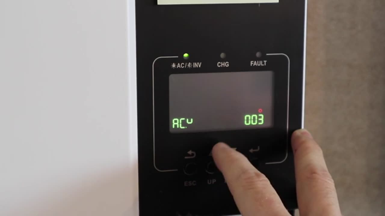
Just a correction: at 6:19, "36" is not a protocol number, its a setting number. To run through your process ... You are at setting #5 (the battery type). You press enter, and the value of that setting is set to US2 (which you correctly say is the User #2 setting, used for dumb lithium batteries, where the battery is controlled by voltage only, not by comms). You press the down arrow and change the setting to LI (Lithium). When you press enter again, you are not looking at a setting of "protocol 36", you are have been jumped to SETTING #36, which is "Protocol" (the left side shows a cryptic "Ptcl" which means PROTOCOL). Here, you are setting the protocol number, in your case to "01".
Protocol numbers (for Growatt and a number of similar all-in-ones) 01, 02, etc up to 49 are variations of the RS485 protocols. This protocol is a request-response protocol (ie the Growatt asks for data, and the battery answers)
Protocols 51, 52, etc up to 99, are variations of the CAN protocol. The CAN protocol is a broadcast protocol, ie the Growatt just listens, and the battery repeatedly broadcasts its requested charge voltage, SOC, requested current, etc etc, and doesn't care if nobody or everybody is listening.
For other readers: If you BMS is a fairly typical BMS of the current era, its likely to have a CAN port, an RS485 port, then an RS232 port (6pin), then a pair of RS485 ports. If so, you can use the BMS port on the Growatt, the CAN port on the battery, and protocol 51 or 52. If your battery only has RS485, or if you want to use RS485, or if your battery/BMS is more reliable over RS485, you can use the BMS port on the Growatt, the RS485 port on the battery, and protocol 01 or 02.
One other correction - you say that older Growatt SPF5000ES used the RS485 port. This is correct, but "which port on the Growatt will work" is comms-board and firmware dependent. Older versions of the comms board and firmware had a limitation where every parallel inverter had to have a cable, and a MODBUS hub did the job of making sure all units saw the same data. Newer comms and firmware, as you correctly mention, share that data over the grey serial cable, so only the master Growatt needs a cable to the battery. The red/black is the cable that allows the inverters to sync their (output) sine wave. It might be more correct to call them frequency sync cables, rather than communication cables.
An important note is that you can't really stuff up the grey cables, as they are gendered. You can stuff up the red/black cables, but I don't know the result of this.
At 8:58 you enter setting 23 (in standby mode) and change to PAL . This is correct, but you are not correct that you "can just esc out" - your setting was not saved, and at 9:01 you can see that the settings have changed back to SIG (inverter in "Single Inverter" mode). This probably worked out OK for you, because (at least with modern firmwares) when the units power up again, and see the grey serial cable is connected, they will know they are in parallel mode and default to PAL. With all settings, the setting is not saved (and also not checked for compatibility with other settings) until you press enter. Note: If you setting is NOT accepted (lets say the value you set is outside the acceptable range, or conflicts), at the point you press ENTER, the setting will change back. Another note: If the setting is READ ONLY (ie setting #2 for a comms battery), when you press ENTER to jump into the value and change it, you will instead end up on the next setting down, in this case setting #3. This is how you know the setting is read only.
Also, with newer firmwares, some settings in the manual that say "This setting is only available when the inverter is in standby mode" are actually settable in both modes. One example is the output voltage; we regularly change the output voltage (setting 08) without turning off the inverter switch - you will get a ~2 sec outage where the inverter stops, then restarts, but you do not need to turn off the switch.
DIS is Disabled, not disconnected, but same same really.
"Setting #11 is only for lead acid batteries" - No, setting 11 is not relevant in your setup, but not because its for lead, its because you don't have a generator or grid backup. Setting #11 is how you control how fast the batteries charge from UTI (utility, aka grid or gen). This enables you to limit how much your Growatt pulls from the generator for recharging (vs running the house).
Setting #12, you are mostly correct, this controls when the grid or generator kicks in, but it wont prevent your battery discharging past X percent - the Growatt is still drawing 80w, and the house is still drawing power. Once you get to setting #12's percentage, the dry contact will change over (potentially starting a gen), and if power is then available on the input terminals, it will start to be used. Now your SOC will rise, but only if gen/grid continues to be present. Its moot, but important: at this point, the battery is STILL being used to run the overhead of the Growatt (~80w per inverter), so if (as in your case) you have no grid and no generator, even if you disconnect the house, you will be slowly dropping in SOC. This might seem like nitpicking, but its important; if you hit #12 at say 6pm in winter, with no grid/gen and a disconnected house, you might need to handle 160w of draw (2 growatts) for another 16 hours until the sun hits your panels again. You can prove this by setting #11 to zero amps, turn off your solar breaker (simulating night) and see that when the battery gets down to #12's set point, the battery is still being drawn down.
Setting #13 is nothing like you describe. This setting is where the generator will stop (the dry contact will be switched back to "normal"), or the grid will stop being used. If you reach as low as setting #21 (probably the setting you were thinking of), the inverter will stop powering the house, and grid/gen will power the house (in bypass mode) and optionally recharge (at the rate of setting #11). If grid/gen is not available, the inverter will still power the house (and the batteries will therefore continue to drop). Once you get some incoming power (solar or grid or gen), its something like 5% (seems to be firmware dependent) above setting #21 that power comes back on (ie the inverter starts inverting again).
I don't understand why you say charging the batteries from grid is not good for them. We charge from grid all the time, also from generator (which is almost the same except the power is not as clean). The SPF5000ES has no dedicated grid-to-battery charger - the grid/gen powers the DC bus, as does the solar, and this bus can handle from 150v to 450v, and DCDC this power down to Vbatt (the specific voltage depends on the battery type, SOC, charge algorithm, and settings 19/20).
There is no problem running the system without PV - this occurs all night, and any time the PV disconnectors are off. We also tell customers not to run without PV but only because it could be weeks before they finish the PV part of the install, and recovering a battery from protection mode (when the voltage is so low the BMS disconnects the cells from the terminals to protect itself) is a pain, so i expect that SS are also saying that to avoid support calls from people leaving the SPF5000ES dragging 80w all day and night, and eventually causing a low battery issue.
-
 LIVE
LIVE
Side Scrollers Podcast
10 hours ago🔴FIRST EVER RUMBLE SUB-A-THON🔴DAY 4🔴BLABS VS STREET FIGHTER!
925 watching -
 LIVE
LIVE
DLDAfterDark
2 hours agoGlock's Decision - How Could It Impact The Industry?
140 watching -
 25:57
25:57
The Kevin Trudeau Show Limitless
1 day agoThe Sound Of Control: This Is How They Program You
32.8K8 -
 8:29
8:29
Colion Noir
12 hours agoThree Masked Idiots Show Up at Her Door — Here’s What Happened Next
40.3K18 -
 15:38
15:38
Cash Jordan
7 hours agoPortland Zombies EMPTY 52 Stores… Mayor FREAKS as “Sanctuary” SELF DESTRUCTS
52.2K59 -
 1:23:21
Precision Rifle Network
1 day agoS5E4 Guns & Grub - Dustin Coleman of ColeTac
10.4K -
 1:09:25
Donald Trump Jr.
8 hours agoCorrupt UN Carbon Tax Exposed, Interview with John Konrad | TRIGGERED Ep.285
156K76 -
 42:58
42:58
TheCrucible
5 hours agoThe Extravaganza! EP: 59 with Guest Co-Host: Rob Noerr (10/23/25)
92.2K7 -
 1:40:59
Kim Iversen
7 hours agoTrump Threatens To End ALL Support For Israel
79K191 -
 13:09:10
LFA TV
1 day agoLIVE & BREAKING NEWS! | THURSDAY 10/23/25
173K23