Premium Only Content

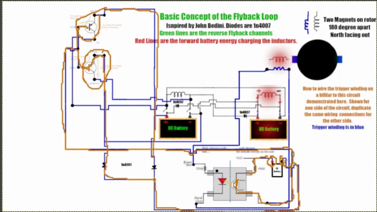
Basic Concept Flyback Loop trigger Winding Explanation with Opto Coupler Live Stream Edit
Flyback Oscillating Loop
(Inspired by John Bedini)
This circuit can be operated solid state or non solid state .
For solid state a Arduino is required or two DPDT Relays will work as well
for non solid state use a rotor with two magnets north facing out 180 degree separation.
Place two bifilar bedini coils 90 degrees apart . Use the trigger winding from each of the two bifilar to trigger two transistors at there base together there by switching the negative and the positive of each coil separately as seen in the animation video .. (There are 4 transistors . Two pairs)
This circuit was originally designed to turn a rotor as there is added energy benefit this way as opposed to solid state . rotor circumference has the two 180 degree drive magnets , rotor face has 3 phase tesla n/s magnet configuration and a 3 phase stator to match with ability to gap the stator for tuning the output AC
Hopefully this makes more sense to people .
OPEN SOURCE
Open Debate
Streamyard Live
-
 26:49
26:49
Energy Works
5 months agoColloidal silver against macrophage infections and biofilms of atypical mycobacteria
601 -
 1:31:56
Michael Franzese
16 hours agoWill NBA do anything about their Gambling Problems?
97.5K20 -
 57:26
57:26
X22 Report
6 hours agoMr & Mrs X - The Food Industry Is Trying To Pull A Fast One On RFK Jr (MAHA), This Will Fail - EP 14
70.2K43 -
 2:01:08
LFA TV
1 day agoTHE RUMBLE RUNDOWN LIVE @9AM EST
129K11 -
 1:28:14
On Call with Dr. Mary Talley Bowden
4 hours agoI came for my wife.
9.33K12 -
 1:06:36
Wendy Bell Radio
9 hours agoPet Talk With The Pet Doc
44.4K24 -
 30:58
30:58
SouthernbelleReacts
2 days ago $6.77 earnedWe Didn’t Expect That Ending… ‘Welcome to Derry’ S1 E1 Reaction
24.4K8 -
 13:51
13:51
True Crime | Unsolved Cases | Mysterious Stories
5 days ago $16.11 earned7 Real Life Heroes Caught on Camera (Remastered Audio)
40.7K10 -
 LIVE
LIVE
Total Horse Channel
15 hours ago2025 IRCHA Derby & Horse Show - November 1st
114 watching -
 4:19
4:19
PistonPop-TV
6 days ago $7.18 earnedThe 4E-FTE: Toyota’s Smallest Turbo Monster
36.6K