VORTEX TURBINE FLUID SYSTEM.
this system uses fluid, stored in a tank in which it enters a vertical spiral, then flows through and out of vortex spirals.
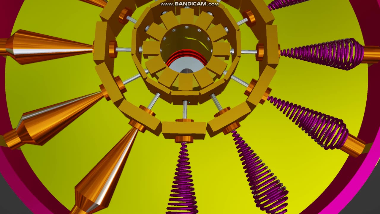
The outwards force of the fluid against the spiral / screw pipes,(vortex's) turns them at a faster rate than the main wheel they are connected to.
e.g. if the main wheel has a radius of 1 meter, and is turning at 500 rpm, the average outwards force of the fluid being pressed against the vortex screw would be over 100 times that of gravity, or 100G
This could create a high volume flow as the main wheel turns.
The vortex 's turn independently, No gears connect them.
half of these vortex's turn in the opposite direction, "unsure if gyroscopic forces would hinder the rotation of the main wheel". if not!, they can all turn in the same direction.
The wheel would be similar to turning a balanced wheel, which would turn as the flow is sucked up into the lower vertical spiral intake that sits in a tank of fluid.
The Vortex wheel itself, is not used to power other external systems that could affect the flow and cause the wheel to stall.
This designed version uses the output flow of the vortex's to turn a second turbine wheel. The high flow and pressure exiting the vortex's hit the blades of the turbine wheel.
The turbine wheel would be used to power external systems. e.g. a generator.
Valves are used to control the speed of the vortex's as well as another valve system ( not shown- still a work in progress) to control the speed of the vortex wheel. (so they don't run to destruction).
Have other variations, including a closed flow system, which would not use a turbine wheel.
the flow itself can be used, prior to entry into the vertical spiral to run other external systems.
There would be no need for a tank.
Still a work in progress.
-
 2:05:29
The Quartering
4 hours agoEscape From New York, Harvard Bombers Caught, Trump DEFIES Court On SNAP, Bomb Threat On Plane!
153K82 -
 LIVE
LIVE
StoneMountain64
3 hours agoBattlefield REDSEC leveling guns for attachments
165 watching -
 16:30
16:30
Clintonjaws
18 hours ago $8.35 earned'The View's' Producer Stops Show & Forces Whoopie To Correct Lie
18.8K16 -
 10:51
10:51
Scammer Payback
2 hours agoScammer's Meltdown after He's Been Hacked
2053 -
 LIVE
LIVE
LFA TV
20 hours agoLIVE & BREAKING NEWS! | TUESDAY 11/4/25
1,329 watching -
 LIVE
LIVE
freecastle
5 hours agoTAKE UP YOUR CROSS- INTEGRITY of the upright GUIDES them, CROOKEDNESS of the treacherous DESTROYS!
122 watching -
 2:04:16
Pop Culture Crisis
3 hours agoCoca-Cola's WAR ON CHRISTMAS, Movie Press Tour CRINGE, Gen Z HATES Gen Z | Ep, 949
13.8K4 -
 1:10:24
Steve-O's Wild Ride! Podcast
5 days ago $0.98 earnedMatt McCusker Makes Steve-O Nervous | Wild Ride #272
13.1K2 -
 17:09
17:09
Bearing
10 hours agoHasan Goes NUCLEAR On Chat ☢️ ROASTED By JD Vance Over Dog Allegations 🚨
18.8K33 -
 1:31:55
The HotSeat With Todd Spears
2 hours agoEP 203: The Military "Whistleblower"
5.01K4