Premium Only Content

12V LED Trouble Light, PCB Details
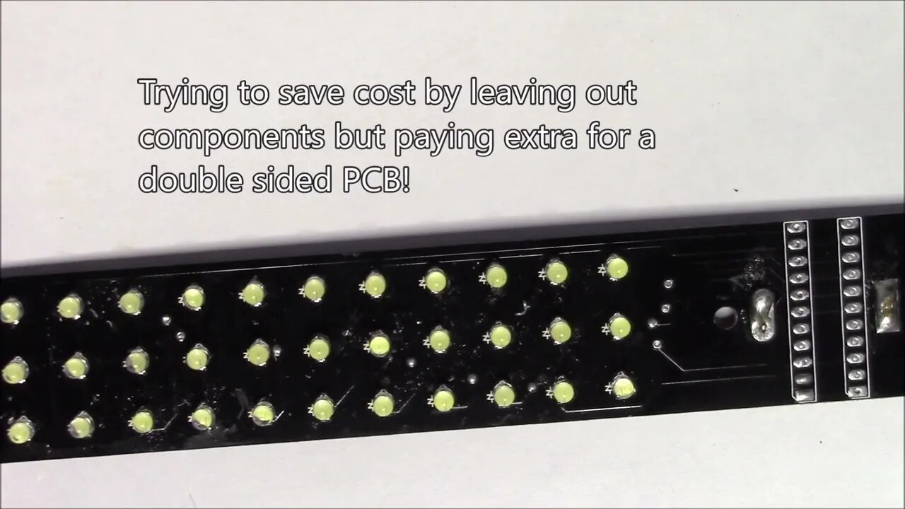
Opening up this 12V trouble light confirmed my suspicions about the internal design. It seems the double sided printed circuit board is overly complicated for the actual circuit. This could have easily been done on a single sided board, 12V trace down one side, 0V trace down the other and then groups of 3 LEDs in series connecting those traces.
It appears that this product was made up of repurposed components. The hard wired power supply had a label indicating it originally had a coax power plug. The circuit board in the light itself seems to be over complex and had nothing in the way of current or voltage regulation. All if had was an on/off push button switch and 60 LEDs wired as 20 strings of 3 in series. I couldn't see that detail from the exterior as there was a paper label inside the tube covering the back side of the PCB.
The original 12V trouble light was purchased around 2005 from Grizzly.com. It came with a hard wired 12V power supply. I figured I could replace that with a lighter plug and use it in the truck. While that did work for a while, it became apparent that the power supply must have had current regulation to keep from over driving the LEDs. As a result, most of the LEDs burned out.
More to come...
Subscribe for more content like this
Comment, like, share & click the bell icon
And as always, thanks for watching
Intro/Outro:
Louisiana Fairytale by Austin Rogers
https://web.archive.org/web/20170402222425/http://drfiddle.com/show_tune.php?id=94
-
 2:27:12
Nerdrotic
10 hours ago $34.48 earnedCIA JFK Assassination Documents | Forbidden Frontier 097
93.1K46 -
 4:02:43
Alex Zedra
7 hours agoLIVE! Verdansk all night <3
36.8K12 -
 1:22:13
Sarah Westall
9 hours agoTruth about Gila Monster Snake Venom & the Miracle of Peptides for Human Health w/ Dr. Diane Kazer
82.7K22 -
 2:18:43
Tundra Tactical
7 hours ago $4.31 earned$3200 ZEV HEARTBREAKER Contest!!!
42.6K1 -
 LIVE
LIVE
EuphioniaStudio
6 hours ago $4.63 earnedIt's BAAAASED, MARIO! | Mario Party 4
704 watching -
 2:48:34
Adam Does Movies
16 hours ago $7.04 earnedAll The Big Movie Announcements From CinemaCon 2025- LIVE!
57.6K -
 1:07:30
Josh Pate's College Football Show
9 hours ago $5.41 earnedBig CFB Changes Coming | USC + Texas + Alabama In 2025 | Truth About Officiating | I Am Engaged
55.3K1 -
 4:43:40
Biscotti-B23
12 hours ago $5.57 earned🔴 LIVE VIEWERS VS MEMBERS BEEF 🔥 FINDING A NEW MAIN ⚔ BLEACH REBIRTH OF SOULS
47.5K2 -
 3:21:55
DTDUBtv
9 hours agoOUTLAST TRIALS WITH SARAHSLOTH17
40.5K1 -
 LIVE
LIVE
Major League Fishing
5 days agoLIVE! - MLF Bass Pro Tour: REDCREST - Day 4
4,527 watching