
Back EMF (Inductive Kickback) In Detail
Since many are asking about it here is my Back emf charging process in fine details, I even try to draw a schematic on the spot that was so asked for.
Little correction on coil, specs, a tongue twister, I say 1.9 ohms instead of 0.9 ohm. Sorry about that!
The point I want to make here is using my method of Back emf, Over unity is possible but you must abide by some rather strict conditions. Such as knowing this is a voltage driven system, If you put any kind of substantial amount of current your going to kill it.
I explain such in the video, Since the back emf generation doesn't care if the duty cycle of the pulse is 50 percent or 1 percent, Knowing this we can save tons of current by limiting to 1 percent. So it takes around 10ma in this configuration to trigger at 1 percent. This is not lots at 12 volts DC input, how ever. With these conditions its not like standard transformer step up v/i action loss. Like we would expect the high voltage side to have less current.
Since we are dealing with back emf radiant sharp spikes, If you look at the scope in my video you will notice virtually no difference in width from the 12 volt input pulse (10 ma current) It looks just like a line on the scope, How ever there is a tiny but of "Width" in this spike, Enough to pass around 10 ma. And when you look at the much higher voltage back emf side. Virtually the same width or in other words same 10ma current but now at 34 volts!! Not a regular transformer action! This can only work with duty cycle of 1% or less or you will quickly find out you use always more current for your input trigger. no more over unity. very sad.
Now you know that at 34 volts 10 ma can do more work then at 12 volts 10ma. So there is your basic "over-unity" concept with this device. From the back emf side.
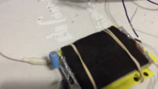
Some folks have asked about the circuit diagram feeding one battery with what appears as a 12 v plus going into the 12 volts minus, that's because I dont show the inverter connected to this battery feeding the 12 volt dc supply this generator operates. That's my method of isolating the two powers and charge at the same time without creating a circuit short on the battery dc and back emf dc pulse. so for back emf pickup with a diode the coil connects to the battery in "reverse" so at the 12 volts plus of the coil this goes to the - 12 volts of the battery, they are isolated. The back emf spike comes back as positive through the diode.
Forum:
http://typeright.social/forum
Please Help Support My Research: https://youtu.be/pYXETBB40j0
-
 4:37
4:37
Joel Lagace
1 year ago $0.02 earned100v Pulsing Cell
198 -
 1:31:37
The HotSeat
13 hours agoBondi On The Hill + Equitable Grading? We Are Failing Our KIDS!
26.2K5 -
 6:05
6:05
Spooky Grandpa's Scary Stories
1 month agoTHE HARVEST MAN (Halloween, Horror, Folklore, Supernatural, Paranormal)
5.5K7 -
 LIVE
LIVE
Lofi Girl
2 years agoSynthwave Radio 🌌 - beats to chill/game to
232 watching -
 1:02:11
DeVory Darkins
12 hours ago $35.50 earnedDemocrats suffers ANNIHILATION during heated hearing with Bondi as Jack Smith bombshell drops
157K107 -
 3:00:07
Price of Reason
12 hours agoJoe Rogan & Theo Von TURN on Trump? Hollywood to STOP Lecturing Viewers? Ghost of Yotei FIASCO!
60.8K8 -
 4:49
4:49
Russell Brand
14 hours agoThis is Unbelievable...
66.8K66 -
 2:55:33
Badlands Media
15 hours agoDEFCON ZERQ Ep. 012: Featuring "AND WE KNOW" and a Special Guest
66K63 -
 2:56:36
TimcastIRL
9 hours agoLEAKED Memo Says NO BACK PAY For Federal Workers Amid Government Shutdown | Timcast IRL
296K204 -
 2:01:55
Inverted World Live
9 hours agoAI Robin Williams, Lab Grown Human Eggs, and Car-Sized Pumpkins | Ep. 119
26.2K7
