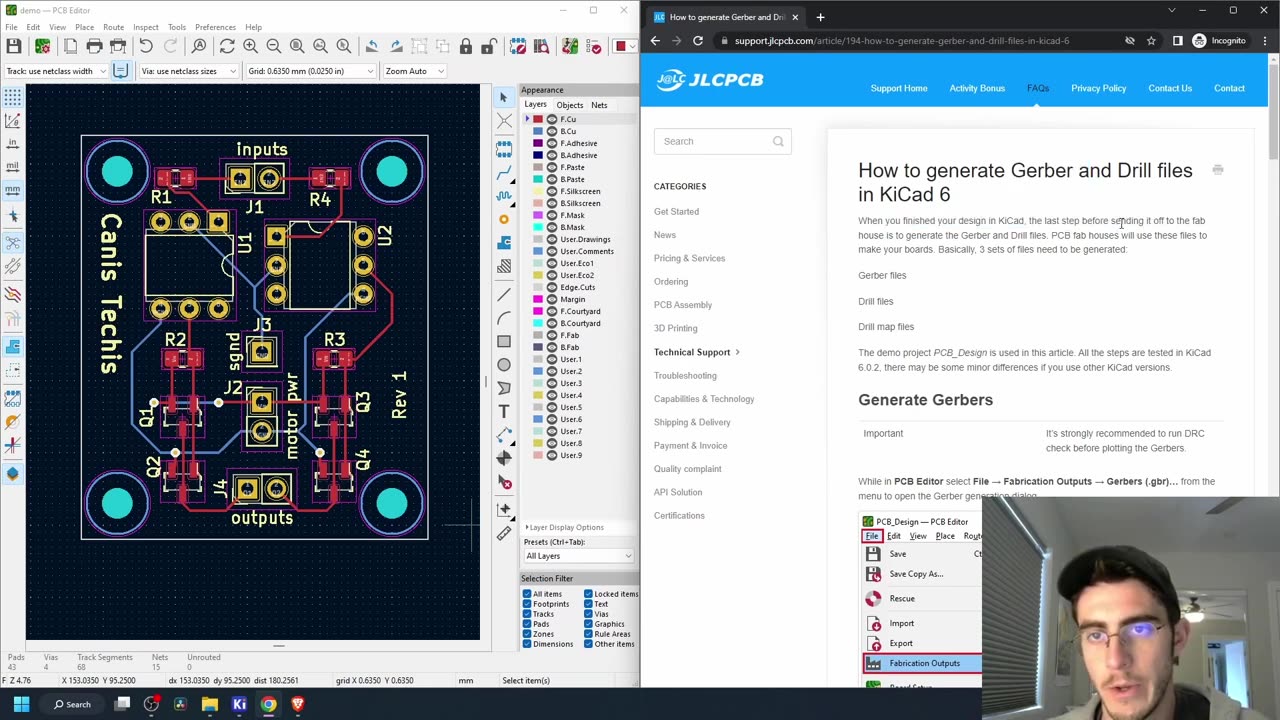
Assembling and Testing ESP32 H Bridge PCB
2 years ago
27.7K
In previous videos, we covered H-Bridge theory, how to make a KiCad schematic, designed a PCB, and generated Gerber files for an H-Bridge design. I decided to modify the design slightly to contain two H-bridges and header pins for an ESP32 microcontroller. I was able to get all SMD components assembled from jlcpcb.com, and soldered the header pins myself in this video. The code I used to test the driver demonstrates that the motor can spin forwards and backwards at set intervals. Enjoy!
Loading comments...
-
 1:53:37
The Quartering
4 hours agoWar Declared On ICE In Chicago, Massive Allegations Against Leftist Streamer Hasan, 600,000 Chinese
120K40 -
 2:04:04
DeVory Darkins
6 hours agoSchumer gets NIGHTMARE NEWS from Democrats
138K51 -
 8:41
8:41
ARFCOM News
5 hours ago $1.32 earnedWill It Dremel? New V-Series Glock Pics Leaked! + ATF Alters The Deal
4.28K3 -
 LIVE
LIVE
LFA TV
20 hours agoLIVE & BREAKING NEWS! | TUESDAY 11/11/25
1,141 watching -
 LIVE
LIVE
freecastle
6 hours agoTAKE UP YOUR CROSS- For the Lord is a GOD of justice; BLESSED are all those who wait for him!
118 watching -
 2:10:12
Side Scrollers Podcast
7 hours agoMAJOR Hasan Allegations + Arc Raiders Review CONTROVERSY + Craig TRENDS on X + More | Side Scrollers
44.5K7 -
 5:43
5:43
Buddy Brown
6 hours ago $6.03 earnedThere's a List of WEF's "Post Trump" Predictions GOING VIRAL! | Buddy Brown
32.5K17 -
 1:43:59
The HotSeat With Todd Spears
3 hours agoEP 207: Have YOU earned THEIR Sacrifice??
14.8K4 -
![[Ep 789] Republicans Turn “Clean CR” Into Hemp Ban | 50 Year Mortgage: Game Changer](https://1a-1791.com/video/fwe2/ce/s8/1/E/2/P/y/E2Pyz.0kob-small-Ep-789-Republicans-Turn-Cle.jpg) LIVE
LIVE
The Nunn Report - w/ Dan Nunn
3 hours ago[Ep 789] Republicans Turn “Clean CR” Into Hemp Ban | 50 Year Mortgage: Game Changer
54 watching -
 12:56
12:56
Benjamin Sahlstrom
8 hours ago $0.67 earnedTesla Powerwall 3 vs Anker SOLIX X1
10.2K