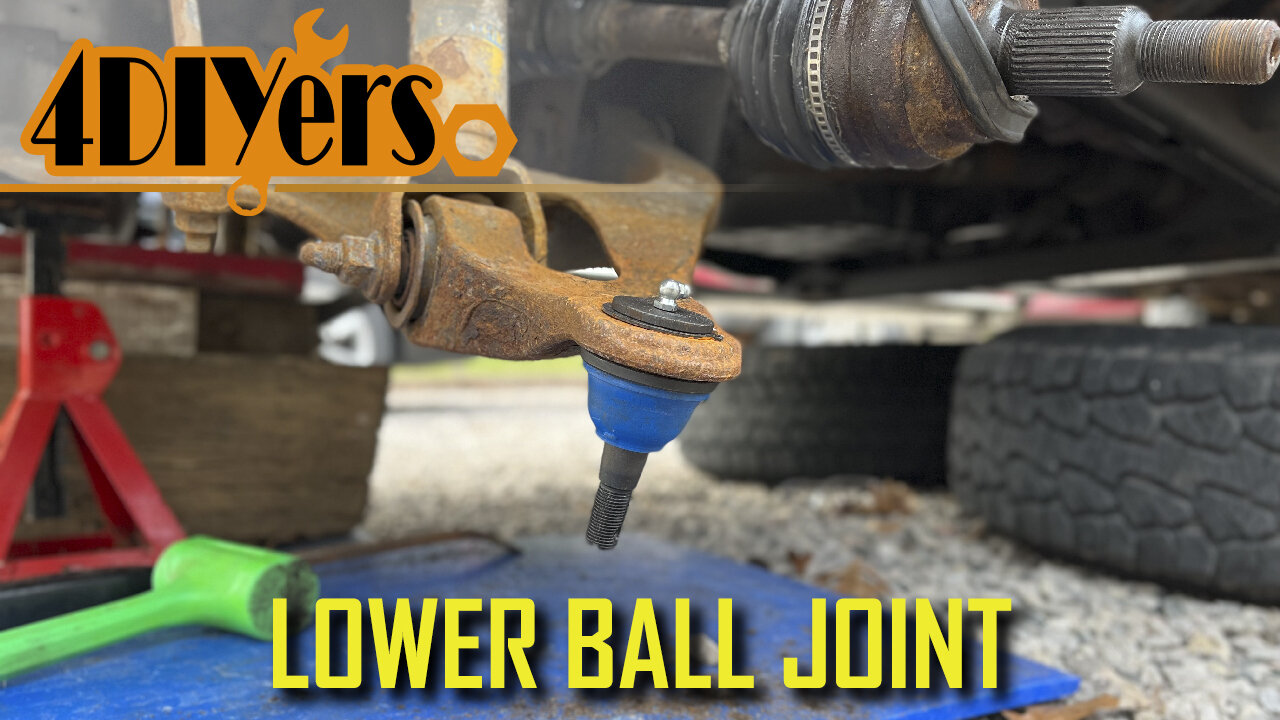
How to Replace the Lower Ball Joints on a 2002-08 Dodge Ram
How to replace the lower ball joints on a third generation Dodge Ram 1500. This is a 2006 4wd model. Loose or worn ball joints can cause uneven tire wear, steering wandering, clunking, stiff steering, and in a severe situation cause the steering knuckle to disconnect while driving. #dodgeram #oemtools #mopar
OEMTOOLS 22649 Pliers Set: https://www.mobiledistributorsupply.com/22649-oemtools-22649-4-piece-pro-mechanic-s-pliers-set-oem
Website: http://4diyers.com
Patreon: https://www.patreon.com/4diyers
Facebook: https://www.facebook.com/4diyers
Twitter: https://twitter.com/4DIYers
Instagram: https://www.instagram.com/4diyers/
Tumblr: http://4diyers.tumblr.com
Pintrest: https://www.pinterest.com/4diyers/
Tools/Supplies Needed:
-new ball joints
-ball joint press
-jack and stands
-21mm and 35mm sockets
-ratchet set
-ball joint separator
-hammer
-large interlocking pliers
-torque wrench
-wire brush
-snap ring pliers
Procedure:
Elevate the front of the vehicle and remove the wheel. Remove the center cap. Reinstall the wheel and lower the wheel down onto the ground.
Using an 35mm socket with a Johnson bar to loosen that axle nut. Elevate the vehicle again and remove the wheel.
Loosen the master cylinder reservoir cap. Loosen the two 21mm bolts holding on the caliper and caliper carrier. Compress the pistons in the caliper using large interlocking players. Remove the caliper assembly and tie it up to the frame using a bungee cord. Remove the rotor.
Remove the cottter pins on the upper ball joint, lower ball joint, and tie rod using pliers. Finish removing that 35mm axle nut.
Use a brass or lead hammer and hit the tip of the axle shaft spline. Using the appropriate sized sockets, loosen the upper ball joint, tie rod, and lower ball joint.
The tie rod was removed. Finish removing the nut on the upper ball joint. Using a ball joint spreader, separate the upper ball joint from the steering knuckle.
Use a strap to hold up the axle once that steering knuckle has been removed.
Use a ball joint seperator to break the lower ball joint free. Disconnect the axle. Then remove the steering knuckle.
Use a wire brush to clean up around the mounting point on the lower ball joint. Using snap ring pliers and a standard screwdriver, remove the snap ring. If equipped with a grease fitting, use a small wrench to remove it.
Using the appropriate attachments to press out the old ball joint. Clean up the area around the ball joint with a wire brush. Compare the old and new ball joints to ensure they are the same. The new ball joint will need to be installed without the grease boot. Make sure the adapters for the ball joint press and the control arm are clean and free of any debris which could potentially fall into the new grease. Use the appropriate adapters to push the new ball joint into place. You can start it into place first with something flat on the top side. Then you’ll need to switch to an adapter which has free movement to push it above the control arm surface for the snap ring. The bottom flange of the ball joint should be firmly pushed against the bottom of the control arm.
Install the grease boot. These are a serviceable ball joint so they do have a grease fitting. Install the grease fitting using a small wrench. Install the new snap ring using snap ring pliers.
Reinstall the steering knuckle. First the axle was pushed back into the wheel bearing and then the lower ball joint was connected. The castle nut was installed by hand so everything is held into place. The lower control arm was jacked up slightly to put some weight on it so it’s easier to connect to the upper control. Thread on the axle nut.
Due to the tension on the bushings you’ll need a prybar to pull down that upper control arm into the steering knuckle. Then the castle nut was installed.
Reinstall all other components in reverse of removal. The upper ball joint torque specification is 40ft lbs or 54 nm. The tie rod nut torque specification is 45 ft lbs or 61 nm. And the lower ball joint torque specification is 38 ft lbs or 52 nm.
Align the holes for the castle nuts on the various components, then install the cotter pins. The torque specifications for the caliper carrier bolts are 130 ft-lbs or 176 nm. The torque specifications for the lug nuts is 135 ft-lbs or 183 nm. The wheel is then lowered onto the ground and as a last step that half shaft nut is torqued to 185 ft lbs or 250 nm.
Thank you to all those who watch my videos and support my content. Don't forget to subscribe to my channel for future tutorial videos and like my video if you found it helpful. New videos are always being uploaded every week!
© 4DIYers 2013
All Rights Reserved
No part of this video or any of its contents may be reproduced, copied, modified or adapted, without the prior written consent of the author.
-
 LIVE
LIVE
tminnzy
10 minutes agoBLACK OPS 7 MULTIPLAYER ROAD TO MASTER PRESTIGE
94 watching -
 47:10
47:10
The Rubin Report
5 hours agoWhat Really Happened on ‘The View’ & ‘Curb Your Enthusiasm’ | Cheryl Hines
158K37 -
 3:08:37
LumpyPotatoX2
4 hours agoWhere Winds Meet: New Level Cap + Rumble Wallet - #RumbleGaming
26.3K1 -
 LIVE
LIVE
SOLTEKGG
2 hours ago🔴LIVE - Battlefield 6 - Going Pro in RED SEC
404 watching -
 11:37
11:37
tactical_rifleman
2 days agoRare Breed BEATS THE ATF | FRT-15 | Tactical RIfleman
62.9K23 -
 2:51:46
Pepkilla
3 hours agoMore GOLD Camo's PLEASE Grind Call Of Black Ops 7
4.1K -
 1:35:54
LexTronic
2 hours ago $0.19 earnedMetroid Prime Remastered
2.73K -
 12:32
12:32
MetatronGaming
17 hours agoBLIGHT looks AMAZING - Trailer Reaction
20.2K12 -
 LIVE
LIVE
ProRedmanX
2 hours ago $0.21 earnedSunday Morning Coffee & Chaos ☕ | PUBG -> BF6 -> ??? #goonsquad
88 watching -
 5:23
5:23
Memology 101
22 days ago $14.21 earnedReporter HUMILIATES Kamala Harris over "WORLD-CLASS" dodge during interview
28.6K50