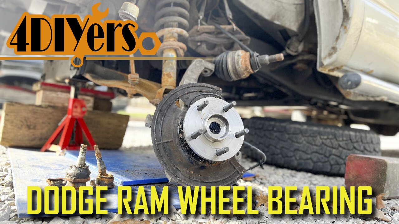
How to Replace the Front Wheel Bearings on a Dodge Ram 1500 4wd
How to eplace the front wheel bearings on a third generation 4wd Dodge Ram. I’m working with a 2006 1500 model. While I was doing the ball joints, I happened to catch light clicking in the wheel bearings so they are coming to the end of their life span. It’s apart now so it’s best to replace them now and save on the extra work after. Worn wheel bearings can cause excessive growling, you can feel some roughness when rotating by hand and they can also cause an ABS fault. I do have a video for what a faulty wheel bearing sounds like so be sure to check it out. #dodgeram #mopar #dodgetrucks
Website: http://4diyers.com
Patreon: https://www.patreon.com/4diyers
Facebook: https://www.facebook.com/4diyers
Twitter: https://twitter.com/4DIYers
Instagram: https://www.instagram.com/4diyers/
Tumblr: http://4diyers.tumblr.com
Pintrest: https://www.pinterest.com/4diyers/
Tools/Supplies Needed:
-35mm, 21mm, 8mm, 18mm sockets
-ratchet set
Procedure:
Remove the wheel. Pop out the center cap. Reinstall the wheel, then lower the wheel down onto the ground. Use a 35mm socket with a Johnson bar to loosen that axle nut. Remove the wheel again.
Loosen the master cylinder reservoir cap. Loosen the two 21mm bolts holding on the caliper and caliper carrier. Compress the pistons in the caliper. Remove the caliper assembly and tie it up to the frame using a bungee cord. Remove the rotor.
Remove the cotter pin on the tie rod, then remove the castle nut and finally disconnect the tie rod.
I removed the fender liner to gain access to the ABS sensor wire. The wheel liner is held on with a couple of 8mm bolts. Push the fender liner down towards the frame and then you’ll be able to unclip it from around the fender. After that is pulling the fender liner straight out.
As for disconnecting the electrical connector for the ABS sensor, there will be a red clip that needs to be pulled out. A standard screwdriver is best for this. Then pull apart the connector.
Remove the cotter pins for the upper and lower control arms, then remove the nuts. A hammer can be used to hit the stud upward for disconnecting the taper on the ball joint. The threaded stud was spinning for the lower ball joint so I ratchet and socket was required while using a wrench to remove the nut. Finish removing the half shaft 35mm nut.
Finally is removing the steering knuckle. Pull the axle shaft out, and make sure the joint doesn’t pull apart.
Using a wire brush, clean up the exposed threads of the three bolts holding on the wheel bearing. Apply some penetrating oil to these exposed threads. By far the easiest method I found was using an impact on all three of these 18mm bolts.
Set up the steering knuckle on a wood block and using a large hammer, hit out the wheel bearing for the backside. Eventually it’ll fall out with the backing plate. If there is any corrosion on the steering knuckle, a file is to efficiently clean it off so we have a clean mounting face for the new wheel bearing. Then I finished up with sandpaper.
All three of those bolts were cleaned up using a wire brush and brake cleaner. Place the new wheel bearing face down, install the dust shield and finally the steering knuckle. Make a note of the orientation for the ABS sensor and dust shield.
I applied a medium grade thread locker to each of the bolts and then install it. They are first tightened up using the electric impact. The torque specification for each of these 18 mm bolts is 120 ft lbs or 163 Newton meters.
Reinstall the steering knuckle. Install the axle spline first, pull the spindle up onto the lower ball joint and thread on the nut. The lower control arm can be jacked up slightly to help push it into place for the upper control arm. Using a prybar, pull down the upper control arm and insert the taper for the ball joint. Thread on the castle nut.
The torque specifications for the upper ball joint torque specification is 40ft lbs or 54 nm, he tie rod nut is 45 ft lbs or 61 nm and th lower ball joint is 38 ft lbs or 52 nm. Install the cotters pins for the upper ball joint, lower ball joint, and tie rod.
Clean the rear of the rotor from any rust and then install. Install the brake caliper with carrier. The torque specifications for the caliper carrier bolts are 130 ft-lbs or 176 nm.
Reconnect the ABS sensor and clip in the wire. The fender liner can then be reinstalled.
Install the wheel. The torque specifications for the lug nuts is 135 ft-lbs or 183 nm. The wheel is then lowered onto the ground and the half shaft nut is torqued to 185 ft lbs or 250 nm. That center cap is installed.
Thank you to all those who watch my videos and support my content. Don't forget to subscribe to my channel for future tutorial videos and like my video if you found it helpful. New videos are always being uploaded every week!
© 4DIYers 2013
All Rights Reserved
No part of this video or any of its contents may be reproduced, copied, modified or adapted, without the prior written consent of the author.
-
 LIVE
LIVE
JuicyJohns
3 hours ago $0.27 earned🟢#1 REBIRTH PLAYER 10.2+ KD🟢
50 watching -
 LIVE
LIVE
Major League Fishing
6 days agoLIVE! - Fishing Clash Team Series: Challenge Cup - Day 5
152 watching -
 LIVE
LIVE
LFA TV
4 hours agoLFA TV ALL DAY STREAM - THURSDAY 8/28/25
4,679 watching -
 LIVE
LIVE
Total Horse Channel
14 hours ago2025 URCHA Futurity | Derby & Horse Show | Thursday
79 watching -
 LIVE
LIVE
The Big Mig™
2 hours agoThe War Powers Resolution w/ David Clements
5,856 watching -
 LIVE
LIVE
Badlands Media
7 hours agoBadlands Daily: August 28, 2025
4,138 watching -
 1:43:15
Dear America
3 hours agoTrans Violence Against Christianity MUST BE STOPPED!!
110K84 -
 LIVE
LIVE
Wendy Bell Radio
7 hours agoGuns Don't Kill People
6,405 watching -
 2:05:38
Matt Kohrs
10 hours agoMarket Open: New Highs or Bust?! || Live Trading Futures & Options
25K2 -
 46:34
46:34
Randi Hipper
2 hours agoWALL STREET'S CRYPTO BET REVEALED! HINT: IT'S NOT BITCOIN!
9.49K2