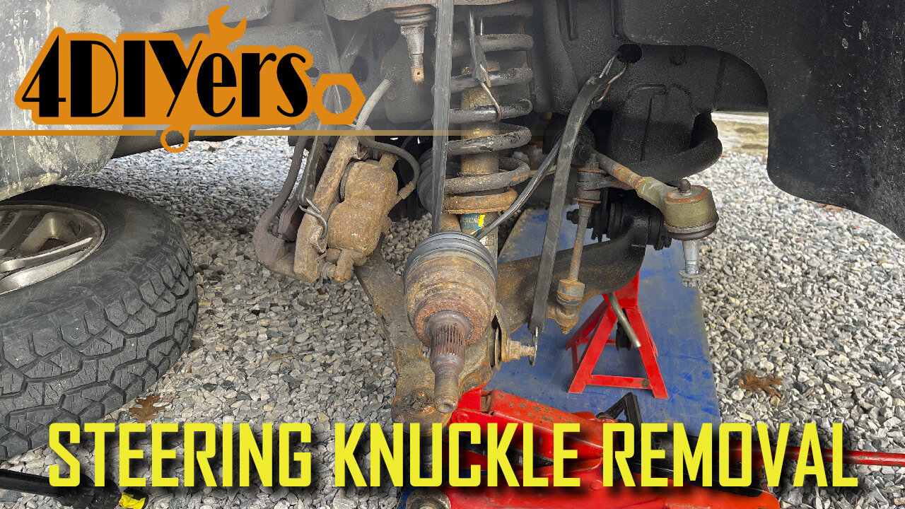
How to Remove the Steering Knuckle on a Dodge Ram
How to remove the steering knuckle on a third generation 4wd Dodge Ram. This particular truck I am working with here today is a 2006 1500 model. #oemtools #dodgeram #dodgeram
OEMTOOLS 24481 1/2" Drive Impact Wrench: https://www.mobiledistributorsupply.com/24481-heavy-duty-1-2-in-drive-jacob-s-chuck-impact-wrench-oem
Website: http://4diyers.com
Patreon: https://www.patreon.com/4diyers
Facebook: https://www.facebook.com/4diyers
Twitter: https://twitter.com/4DIYers
Instagram: https://www.instagram.com/4diyers/
Tumblr: http://4diyers.tumblr.com
Pintrest: https://www.pinterest.com/4diyers/
Tools/Supplies Needed:
-22mm, 35mm sockets with ratchet
-brass hammer
-wire brush
-torque wrench
-jack with axle stand
-large interlocking pliers
-pliers
-medium grade threadlocker
Chapters:
00:00 Intro
00:16 Wheel Removal
00:56 Half Shaft Nut Removal
01:15 Brake Removal
01.49 Ball Joint & Tie Rod Separation
02:55 Steering Knuckle Removal
03:07 Steering Knuckle Installation
Procedure:
Elevate the front of the truck. Loosen and remove the 22 mm lug nuts. Remove the wheel and pop out the center cap. Reinstall the wheel and tighten the lug nuts. Lower the wheel back onto the ground. Using a 35 mm socket with a Johnson bar, loosen that axle nut.
Jack up the wheel and remove. Crack the master cylinder reservoir cap to relieve any pressure when compressing the caliper pistons. Use a 22 mm socket with a half inch drive ratchet to loosen and remove those caliper carrier bolts.
Compressed the pistons in the caliper using large interlocking pliers. Remove the caliper, pad, and carrier assembly. Tied it up to the frame so it’s not hanging by the rubber flex line.
Remove the rotor. Place it somewhere safe so it doesn’t come into contact with any oil or grease. If your ball joints and tie rod are equipped with castle nuts, you will need to remove the cotter pins. They may also be equipped with stover nuts therefore there are no pins needed to be removed.
Remove the tie rod. The nut was made flush with the stud, and it was hit with a hammer to disconnect a taper. Then place it off to the side.
Remove that half shaft axle nut. If the spline is stuck into place, you can use a lead or brass hammer to help break it free.
Remove the nut for the upper ball joint. A pickle fork or ball joint separator can be used to break this connection free. You may even be able to use a hammer to hit upward on the threaded stud. Keep in mind this is under tension so it will spring back.
I had to make extension arms for my ball joint separator as it wasn’t large enough for the lower ball joint. A tool is available for this however at the time of this disassembly, it was on backorder for over six months.
Once disconnected, then remove the steering knuckle and disconnect the spline for the half shaft. Use a strap to hold the axle in place so it doesn’t come apart.
As for reassembly, the spline is slid into place in the wheel bearing assembly.
The steering knuckle is then lifted to the lower ball joint and then the castle nut is installed. I jacked up the lower control arm to put some tension on the suspension so it’s easier to install the upper ball joint.
Medium grade thread locker is applied to the half shaft threaded portion and then the nut is installed. Use a pry bar to pull down the upper control arm. The coil spring was used as a leverage point. Once it’s in place, install the castle note.
Then is install the tire rod. Tighten the upper ball joint. The upper ball joint torque specification is 40ft lbs or 54 nm. Tighten the tie rod. The tie rod nut torque specification is 45 ft lbs or 61 nm. Tighten the lower ball joint. The lower ball joint torque specification is 38 ft lbs or 52 nm.
The rotor is then reinstalled. A wire brush is used to clean away any rust or debris so we don’t have any runout. If you have old hubs, a wire brush is recommended to be used on these.
Install the caliper assembly. The torque specifications for the caliper carrier bolts are 130 ft-lbs or 176 nm. Install the wheel. You may need to clean the hub mounting face in the wheel to ensure there’s no runout again. Considering these are aluminum wheels, I would recommend using a brass wire brush. The torque specifications for the lug nuts is 135 ft-lbs or 183 nm. Finally is tightening that half shaft axle nut. The half shaft nut torque specification is 185 ft lbs or 250 nm.
Reinstall the center cap and then lower the vehicle back onto the ground.
Thank you to all those who watch my videos and support my content. Don't forget to subscribe to my channel for future tutorial videos and like my video if you found it helpful. New videos are always being uploaded every week!
© 4DIYers 2013
All Rights Reserved
No part of this video or any of its contents may be reproduced, copied, modified or adapted, without the prior written consent of the author.
-
 1:07:06
Mike Rowe
18 days agoThe Fight For America's Heartland | Salena Zito #442 | The Way I Heard It
30.3K47 -
 2:43:30
TimcastIRL
5 hours agoSouth Park Goes FULL CHARLIE KIRK, Latest Episode ROASTS Trump Again | Timcast IRL
210K77 -
 LIVE
LIVE
SpartakusLIVE
6 hours agoThe Return of the KING of Content
446 watching -
 10:05
10:05
MattMorseTV
9 hours ago $6.53 earnedHe actually did it...
55.1K23 -
 1:32:39
Anthony Rogers
1 day agoEpisode 376 - Todd Schowalter
25.7K -
 3:42:07
megimu32
5 hours agoOTS: Movie Tie-In Games + Remakes: Let’s Play Memory Lane
41.1K5 -
 1:15:06
Adam Does Movies
12 hours ago $1.02 earnedTalking Movies + Ask Me Anything - LIVE
28.6K1 -
 1:17:18
Glenn Greenwald
1 day agoWhat are CBS News' Billionaire Heirs Doing with Bari Weiss? With Ryan Grim on the Funding Behind It; Europe Capitulates to Trump Again | SYSTEM UPDATE #494
113K83 -
 1:43:49
RiftTV
7 hours agoCNN Calls Black NY Shooter WHITE, Cincinnati FATIGUE | The Rift | Guest: Braeden Sorbo, 2Protects1
53.2K15 -
 4:21:04
LumpyPotatoX2
8 hours agoKilling Floor 3: Rampage & Chaos - #RumbleGaming
19.5K1