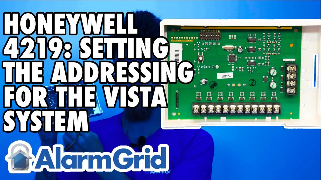
Honeywell 4219: Setting the Address for a VISTA System
In this video, Dylan from Alarm Grid will discuss how to set the dip switches on a Honeywell 4219 8-zone expander. Because multiple 4219 expanders can be used on each panel, there must be some way for the panel to tell one module from another. This is where addressing comes into play. Based on the instructions provided with the VISTA panel, each segment of eight (8) zones uses a different address.
The first set of zones that can be used with the 4219 is zones 9 - 16. When using a 4219 for this group of zones, the address for the 4219, as determined by the dip switches, must be set to seven (7). For zones 17 - 24, the dip switches must be set to address eight (8). For Zones 25 - 32, the dip switches must be set to address nine (9). For Zones 33 - 40, the module uses address ten (10), and for zones 41 - 48 it uses address eleven (11). Also, note that the VISTA-15P panel can only support up to two (2) of these modules using zones 9 - 16 and 17 - 24 and the corresponding addresses for those two sets of zones.
The 4219 has been around for many years. There have been a couple of different variations to the module over the years. Older modules may only have five (5) dip switches. These modules used a 1kΩ resistor and the use of the resistor was mandatory. They also had a jumper that enabled or disabled the tamper switch, as opposed to a dip switch. Regardless of which module version you may have, the address settings will all be the same, and will use the same dip switch numbers.
In this video, the module is shown with the dip switches upside down. You may notice what looks like the word NO on the lower right side of the dip switch block. This is actually the word ON, and shows that when the dip switch handle is placed toward this side of the block, it is ON. Armed with that information, you can properly set the dip switches for your configuration.
When changing the dip switch settings, it is best to power the unit down, change the switch settings, and then power it back on. You'll need a small screwdriver, or a fingernail to change the position of the dip switches.
Dip switch 1 determines the response time for the first zone on the 4219. When the dip switch is set to ON, the first zone will have a normal response time of 300ms. If the dip switch is set to OFF, the first zone will have a fast response time of 10ms. A fast response time is required for certain sensors, such as inertia-style shock sensors. In most applications, dip switch 1 can be set to ON.
Dip switches 2 - 5 determine the module address. Please refer to the FAQ linked at the bottom of this description for a full explanation of each address setting. Also, please note that on newer 4219s there is an LED that is ON when the address is set to seven (7) and is OFF when the address is set to eight (8). Whether the LED is lit or not is determined by dip switch 2. This LED can let you know that the 4219 has power, but otherwise, it doesn't really indicate anything other than the dip switch 2 setting. If dip switch 2 is ON, the LED is OFF. This is as designed.
Dip Switch 6 should always be ON for VISTA-15P, VISTA-20P, and VISTA-21iP or VISTA-21iPLTE panels.
Dip Switch 7 determines if the module will use End-of-Line Resistors (EOLR) or not. ON = No EOLR, OFF = 2kΩ EOLR required for each zone. With this, it's all zones use resistors, or no zones use them.
Dip Switch 8 determines if the cover tamper is enabled or disabled. Dip switch 8 ON = Tamper Disabled. Dip Switch 8 OFF = Tamper Enabled. If the 4219 is to be mounted inside the metal enclosure with the panel, then you can install it without the plastic cover and the tamper should be disabled. If the 4219 is mounted outside the metal enclosure where it may be vulnerable to tampering, then you want to be sure to insert the magnet in the cover and use the cover for the 4219 with the tamper feature enabled.
https://www.alarmgrid.com/faq/how-do-i-address-a-4219-zone-expander-to-a-vista-system
-
 4:37
4:37
Alarm Grid Home Security DIY Videos
2 years agoQolsys IQ Panel 4: Change the Master Code
35 -
 LIVE
LIVE
DLDAfterDark
2 hours agoThe AR15 BurnDown That Will Leave You Speechless!
130 watching -
 1:48:12
megimu32
2 hours agoON THE SUBJECT: Throwback Thursday | Wheel of Nostalgia Chaos!
7.92K4 -
 LIVE
LIVE
Flyover Conservatives
22 hours agoTrojan Horse in the Big Apple? Prophetic Warning w/ Robin D. Bullock | FOC Show
1,841 watching -
 1:31:48
Precision Rifle Network
1 day agoS5E6 Guns & Grub - The Boys Are Back!
4.73K3 -
 LIVE
LIVE
SynthTrax & DJ Cheezus Livestreams
4 days agoLumines - Arise - DJ Cheezus Birthday Stream
134 watching -
 1:00:41
Glenn Greenwald
7 hours agoEXCLUSIVE: Succession Actress & Podcast Host Dasha Nekrasova Speaks Out About Hollywood Cancellation Over Fuentes Interview | SYSTEM UPDATE #549
109K78 -
 31:27
31:27
Robbi On The Record
9 hours ago $0.02 earnedWhat the Bible say about Astrology.. The Conversation Culture Has Been Avoiding | ft. JT Follows JC
20.2K4 -
 LIVE
LIVE
SOLTEKGG
2 hours ago🟢 Live: Pro Player Returns to Battlefield 6 RED SEC
89 watching -
![Gray Zone Warfare [RGMT CONTENT Mgr. | RGMT GL | GZW CL]](https://1a-1791.com/video/fww1/bd/s8/1/m/O/L/B/mOLBz.0kob-small-Gray-Zone-Warfare-RGMT-CONT.jpg) 2:16:25
2:16:25
XDDX_HiTower
2 hours ago $0.47 earnedGray Zone Warfare [RGMT CONTENT Mgr. | RGMT GL | GZW CL]
9.17K