Voltage Multiplier Circuit Explained (Voltage Doubler, Voltage Tripler and Quadrupler Circuits)
In this video, the voltage multiplier circuits (Voltage Doubler, Voltage Tripler, and Voltage Quadrupler Circuits) and their working have been explained.
By watching this video, you will learn the following topics.
0:21 What is Voltage Multiplier Circuit?
1:41 Application of Voltage Multiplier Circuits
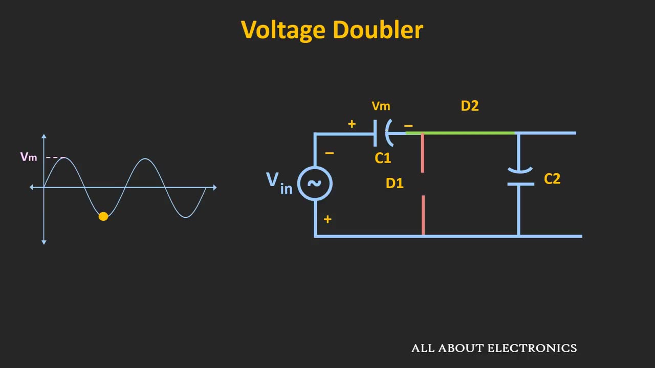
2:32 Voltage Doubler Circuit
8:40 Voltage Tripler and Quadrupler circuit
What is the Voltage Multiplier Circuits?
The voltage multiplier circuit gives DC output which is N times the input signal. The input to such circuit is the AC signal. And the output is N times the peak amplitude of the AC input signal.
These circuits are designed using the diodes and the capacitors and they are preferred in the applications with a very light load. (Current in mA Range)
Applications of Voltage Multiplier circuits:
1) Cathode Ray Tubes (CRT)
2) Bug Zapper Circuits
3) Printers and Photocopy machines
4) In high energy physics experiments
In this video, the Voltage Doubler, Voltage Tripler and Voltage Quadrupler circuits have been explained.
For each circuit during the design, if Vm is the peak amplitude of the applied AC input signal, then the Peak Inverse Voltage (PIV Rating) of each diode should be at least equal to 2Vm.
This video will be helpful to all the students of science and engineering in understading the working of the Voltage Multiplier Circuit.
#VoltageMultiplierCircuit
#VoltageDoubler
#VoltageTripler
-
 1:44:36
Megyn Kelly
1 day agoRemembering Charlie Kirk, with Tucker Carlson, Donald Trump Jr., and Benny Johnson
48.1K109 -
 9:40
9:40
Lara Logan
2 hours agoHonoring Charlie Kirk - Going Rogue with Lara Logan - LIVE
28.3K35 -
 3:03:45
The Charlie Kirk Show
6 hours agoCharlie Kirk: A Life of Faith, A Legacy That Endures
451K407 -
 3:58:08
The Rubin Report
7 hours agoCharlie Kirk’s Best Moments on The Rubin Report
68.5K27 -
 UPCOMING
FomoTV
18 hours ago🕯 Charlie Kick Assassinated — Radical Campus Rhetoric Made This Possible | Fomocast 09.11.25
18.8K3 -
 3:08:36
Right Side Broadcasting Network
7 hours agoLIVE REPLAY: Latest News from the Trump White House - 9/12/25
76.3K24 -
 LIVE
LIVE
Dr Disrespect
6 hours ago🔴LIVE - DR DISRESPECT DESTROYS BORDERLANDS 4 - INSANE LOOT, CHAOS & RAGE
1,087 watching -
 1:28:34
Mark Kaye
6 hours ago🔴 How Charlie Kirk's Killer, Tyler Robinson, Was Caught!
53.3K49 -
 59:58
59:58
Jeff Ahern
3 hours ago $1.80 earnedFriday Freak out with Jeff Ahern
22K1 -
 1:29:00
Russell Brand
7 hours agoLaura Loomer: The Most Banned Woman in the World - SF632
98.2K154