Premium Only Content

Flyback Generator Myke Does John Bedini modified Updated
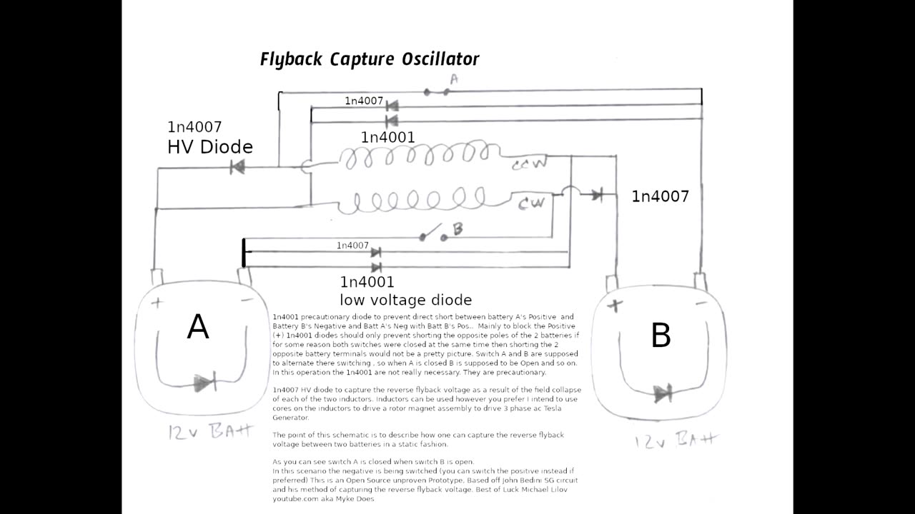
This is a reverse flyback capture circuit designed to capture the flyback between two inductors and two batteries . The point of this circuit is to show how you can capture the flyback avoiding the need to swap the battery positions as done with the single inductor Bedini SG circuit. You could call this a dual inductor Bedini circuit . The addition of the second inductor makes it possible to bounce the flyback between the two batteries using this circuit design . This is open source un proven un built prototype . And open for debate and experiment as to if the 1n4001 blocking diodes are necessary. Have Fun :) (added HV Diode 1n4007 to capture neg flyback voltage ) This circuit main focus is to capture the flyback in alternation between the 2 inductors and the 2 batteries . The Inductor EMF fields can be used how one pleases . (Drive ROTOR Etc or generate AC)
Red indicates forward battery voltage (Source energy is Battery)
Blue indicates reverse flyback voltage (Source Energy is the Reverse Flyback )
This circuit has been updated . See 4 transistor circuit in library . This circuit acts like efficient motor driver much like the Atoms motor captures the flyback into alternate drive inductors this circuit does the same essentially when one inductor is pulsed forward the flyback reverse pulses the other coil virtually simultaneously, if you want the flyback to instead fall into alternate battery as opposed to alternate drive coil see 4 transistor circuit in library
-
 LIVE
LIVE
SpartakusLIVE
9 hours agoI’M BACK || ONLY Solos on WZ - NO BLOPS7, NO REDSEC, NO ARC, NO FRIENDS
2,232 watching -
 LIVE
LIVE
The Connect: With Johnny Mitchell
10 hours ago $3.07 earnedAmerican Vigilante Reveals How He Went To WAR Against The WORST Cartels In Mexico
209 watching -
 LIVE
LIVE
BlackDiamondGunsandGear
4 hours agoITS MA'AM!! / After Hours Armory / Are you threatening me?
197 watching -
 44:54
44:54
SouthernbelleReacts
8 days ago $0.19 earnedHIS RUG… I CAN’T STOP LAUGHING 🤣 | Big Lebowski Reaction
3.9K8 -
 2:17:46
megimu32
3 hours agoOFF THE SUBJECT: Reddit Meltdowns, Music Takes & Bodycam Breakdowns
25.2K5 -
 LIVE
LIVE
The Rabble Wrangler
8 hours agoRedSec with Mrs. Movies | The Best in the West Carries His Wife to Victory!
144 watching -
 LIVE
LIVE
DLDAfterDark
2 hours ago $0.74 earnedTrans Man's Death Threats To Christian Conservatives - Whistlin' Diesel Tax Evasion
198 watching -
 23:42
23:42
Robbi On The Record
2 days ago $6.22 earnedWhat's happening in the republican party?? BTS of Michael Carbonara for Congress
53.2K11 -
 4:53
4:53
PistonPop-TV
2 days ago $1.10 earnedThe G13B: The Tiny Suzuki Engine That Revved Like Crazy
6.71K -
 LIVE
LIVE
GritsGG
4 hours ago#1 Most Warzone Wins 4000+!
212 watching