Premium Only Content

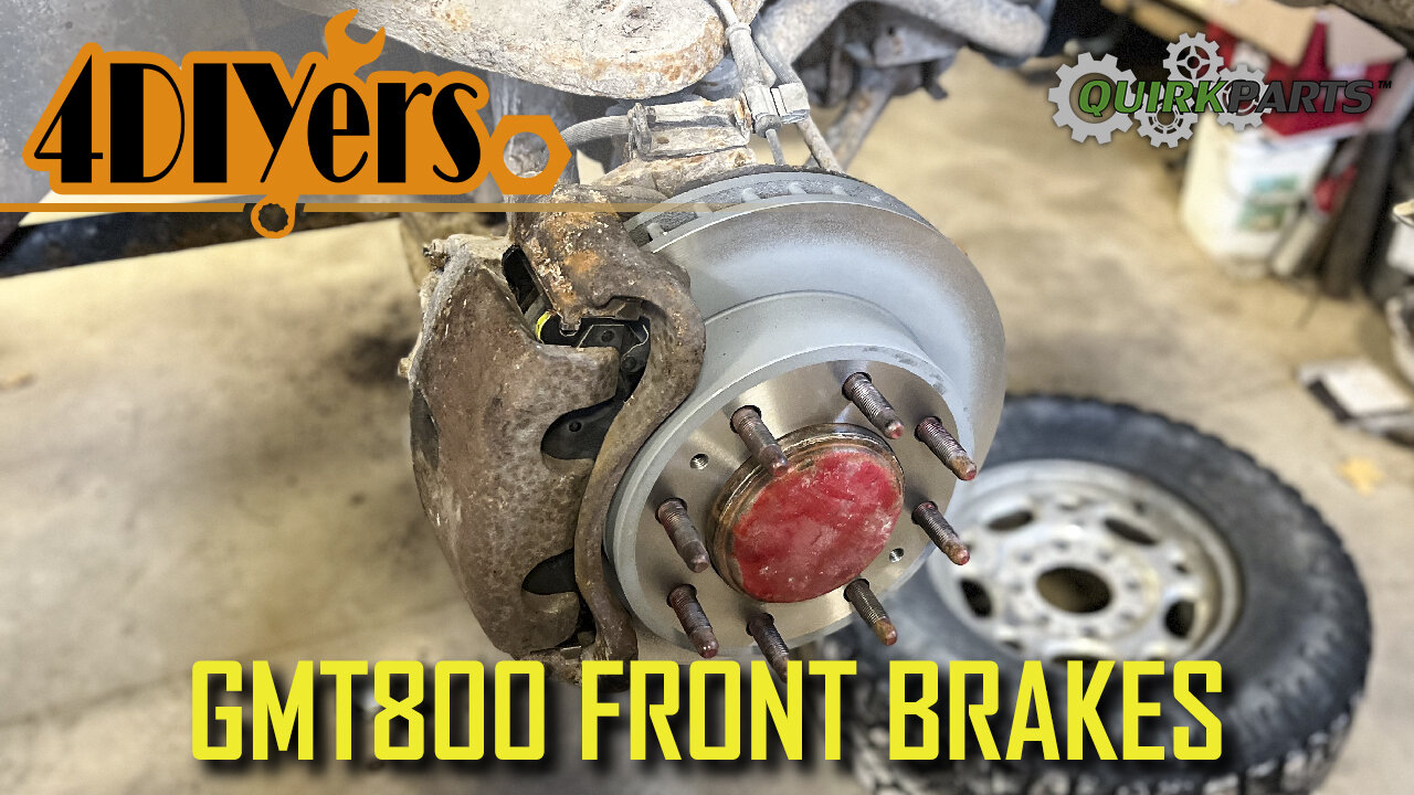
How to Replace the Front Brakes on a GMC Sierra 1500HD GMT800
How to replace the front pads and rotors on a 2005 GMC Sierra 1500HD. This is a second generation Sierra, the same process can also be applied to the Chevrolet Silverado HD as well as other GMC brands such as the Suburban or Yukon, Express or Savanna, etc. #gmt800 #quirkparts #gmcsierra #chevroletsilverado
5% discount code: DIY5
Front pads (84292732): https://www.quirkparts.com/oem-parts/gm-oem-new-gm-99-17-cadillac-chevrolet-gmc-hummer-front-disc-brake-pad-kit-84292732-84292732?utm_source=youtube.com&utm_medium=affiliate&utm_campaign=4DIYers&utm_term=front_pad_84292732
Front rotors (15942195): https://www.quirkparts.com/oem-parts/gm-oem-new-1999-18-gm-cadillac-chevrolet-rotor-front-and-rear-wheel-brake-15942195-15942195?utm_source=youtube.com&utm_medium=affiliate&utm_campaign=4DIYers&utm_term=front_rotor_15942195
Website: https://www.quirkparts.com/?utm_source=youtube.com&utm_medium=affiliate&utm_campaign=4DIYers&utm_content=homepage
Website: http://4diyers.com
Patreon: https://www.patreon.com/4diyers
Facebook: https://www.facebook.com/4diyers
Twitter: https://twitter.com/4DIYers
Instagram: https://www.instagram.com/4diyers/
Tumblr: http://4diyers.tumblr.com
Pintrest: https://www.pinterest.com/4diyers/
Tools/Supplies Needed:
-18mm, 21mm, & 22mm socket
-hammer
-new pads and rotors
-wire brush
-copper anti-seize
-brake cleaner
-ratchet
-torque wrench
Procedure:
Start by elevating the front of the vehicle, using a 22mm socket, remove the center cap from the wheel. Remove the 8 22mm lug nuts. Finally remove the wheel.
It’s always a good idea to crack the master cylinder receiver cap to relieve any potential pressure build-up when compressing the pistons in the caliper. Using large interlocking pliers or a screwdriver, compress the pistons back slightly to make the removal process easier.
Using a ratchet, remove the 2 18mm bolts holding on the caliper to the carrier. These also function as the slide pins so there will be grease when they’re removed. Remove the caliper. Hang the caliper up, either on the upper control arm or using a hook or bungee cord. Do not hang the caliper on the line as this can cause unwanted stress to the flex line potentially damaging it.
Remove the pads. A standard screwdriver is used to remove the anti-rattle clips. Now the carrier can be removed. You may need a breaker bar for these if they are seized. These are held on with 2 21mm bolts.
If the rotor is stuck and you are keeping it, hit between the wheel studs to break any rust free. If you’re not keeping the rotor, then you can hit the breaking surface. Remove the rotor.
Once that rotor has been removed, clean the hub surface using a wire brush or wheel. This will ensure there won’t be any runout when installing the new rotor. Wash the area with brake cleaner.
This is optional and does help if you live in an area that experiences winters where your vehicle is exposed to salt. A light layer of copper anti-seize can be applied to the hub surface, preventing the rotor from becoming seized to the hub face.
Before the rotor is installed, the braking surface is cleaned with brake cleaner and a clean rag to remove the packaging oil. Install the rotor.
Use a couple of lug nuts to hold it in place, this will help with the reassembly of the carrier with pads and caliper.
Use a wire brush or wheel to clean the carrier, specifically the area where the anti-rattle clips will be installed. These must be cleaned so the pads move freely and do not bind. Install the carrier along with the 2 21mm bolts. The torque specification is 139 ft-lbs or 188 NM.
Install the new clips. Silicone grease does come supplied with the new pads, which get applied to the tabs where they’re in contact with the anti-rattle clips. Install the new pads.
Using an old pad and gear clamp, compress the pistons in the caliper fully. Install the caliper. The old slide pins are cleaned to remove the old grease. Then silicone grease is applied to these as well. Also, inspect these for any wear or damage and replace them as needed. The bolts are then tightened here. The torque specifications are 80 ft-lbs or 108 NM.
Clean the backside of the wheel to remove any dirt or rust which may cause runout. Install the wheel. The torque specifications are 140 ft-lbs or 190 NM. Install the center cap when done.
Thank you to all those who watch my videos and support my content. Don't forget to subscribe to my channel for future tutorial videos and like my video if you found it helpful. New videos are always being uploaded every week!
© 4DIYers 2013
All Rights Reserved
No part of this video or any of its contents may be reproduced, copied, modified or adapted, without the prior written consent of the author.
-
 14:47
14:47
GritsGG
8 days agoRumble Tournament Dubular! Rebirth Island Custom Tournament!
110K6 -
 2:03:11
Inverted World Live
10 hours agoY2K 2.0 | Ep. 104
132K9 -
 2:02:53
Badlands Media
14 hours agoBaseless Conspiracies Ep. 149: Epstein Docs, Charlotte Stabbing, and Trump’s Next Moves
52.7K18 -
 2:56:12
TimcastIRL
9 hours agoTrump SLAMS Democrats Over Irina Zarutska Killing, Says WAR Over Chicago Crime | Timcast IRL
199K123 -
 29:08
29:08
Afshin Rattansi's Going Underground
1 day agoCol. Lawrence Wilkerson: World War 3 is ALREADY HERE, Netanyahu is INTENT on Greater Israel
27.3K26 -
 7:24:49
SpartakusLIVE
10 hours agoNONSTOP Snipes, Rockets, and BICEPS = Monday MOTIVATION
79.6K1 -
 6:31:35
Rallied
11 hours ago $4.21 earnedSolo Challenges All Day
64.5K2 -
 1:27:53
Flyover Conservatives
14 hours agoIs AI Actually Alien Intelligence? Dr. Jason Dean Exposes the Dark Side | FOC Show
55.5K8 -
 1:47:36
Glenn Greenwald
11 hours agoJD Vance and Rand Paul Clash on Due Process: War on Terror Echoes; Has the U.S. Given Up on Confronting China? Ben Shapiro's Latest Falsehoods About Israel | SYSTEM UPDATE #510
120K95 -
 LIVE
LIVE
RaikenNight
8 hours ago $6.85 earnedExploring the Galaxy of No Mans Sky
916 watching