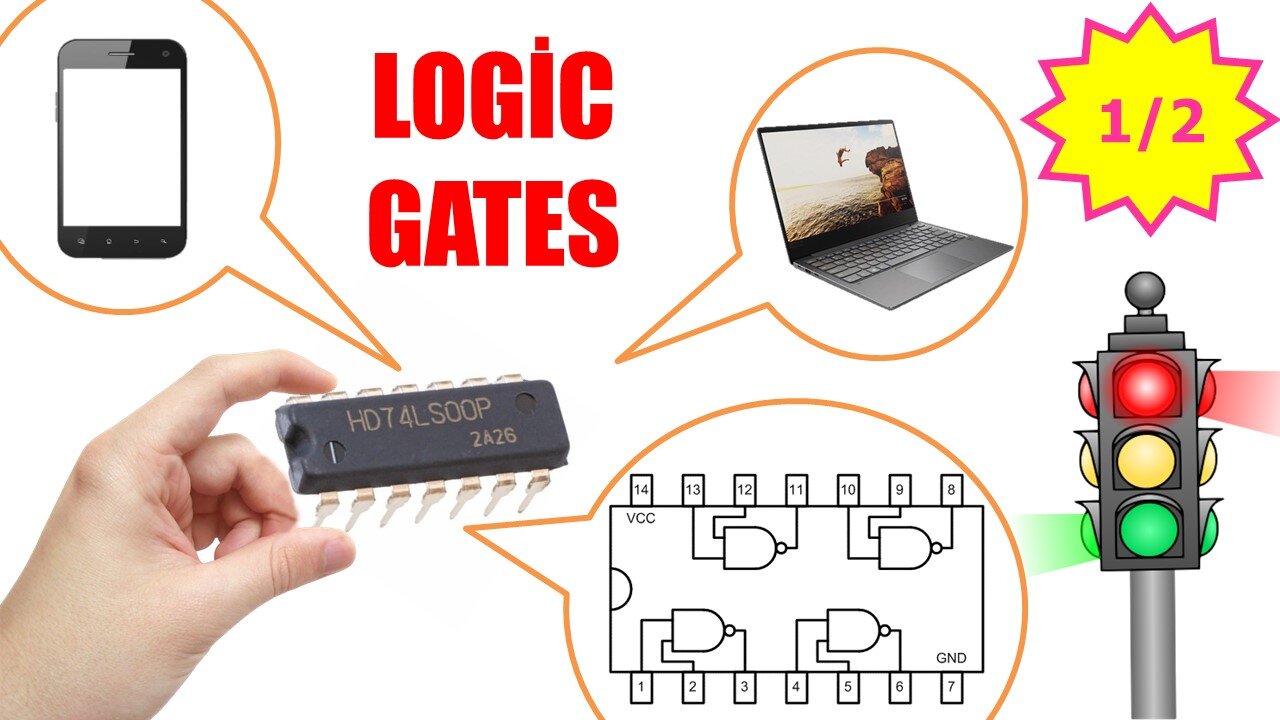
Logic Gates (AND, OR, NOT Gates) Part 1/2
In this video, I will explain the working principle of logic gates that form the basis of all electronic devices we use, which we can encounter in many areas in daily life. When we say digital electronics, the first thing that comes to our mind is logic gates. When numerical expressions are mentioned, level 1, level 0, logic circuits or in other words logic gates come to mind. This type of integrated circuit consists of circuits made with basic electronic elements such as transistors, resistors and diodes.
Logic gates form the basis of digital systems. Input information is transferred to the output by performing Boolean mathematics operations. Operations are performed on the logical expressions Logic-1 and Logic-0. The reciprocal of 1 logic expression is defined as 5V, and the reciprocal of 0 logic expression is defined as 0V.
Now let's look at how to number the pins of the logic gates. When we hold it to read the text on the IC, there is a notch on the left side. The pins are numbered starting from this notch. Logic gate ICs are generally 14 pins.
For example, when we look at the internal structure of the 7408 IC, we see that it consists of four AND gates. This logic gate has two inputs and one output. When we go into a little more detail and look inside an AND gate, we see that there is a circuit consisting of two BJT transistors and resistors.
There are 7 types of basic logic gate circuits: They are the AND gate, OR gate, NOT gate, NAND gate, NOR gate, XOR gate, and finally the XNOR gate. These circuits, also known as logic gates, produce appropriate logical results with 1 and 0 data received from the input, namely 5V and 0V, within a certain Boolean Algebra framework. That is why we can say that they are indispensable elements of digital electronic systems. Now, let's examine the symbols, mathematical expressions and truth tables of these logic gates one by one. In order for the video not to be too long and boring, I will explain the AND, OR and NOT gates in this video. In the next video, I will explain other logic gates.
00:00 Introductor
02:29 AND Gate
04:55 OR Gate
06:40 NOT Gate
#logic #gates #electronics
-
 5:24
5:24
Electrical Electronics Applications
2 years ago $0.02 earnedHow to Calculate Capacitance and Voltage Value of Capacitor?
189 -
 LIVE
LIVE
Side Scrollers Podcast
1 hour agoAsmongold/DSP RESPONSE + Kaceytron’s Life IMPLODES + Lunduke Gets Threats + More | Side Scrollers
7,923 watching -
 29:48
29:48
The White House
1 hour agoPresident Trump and The First Lady Participate in the Thanksgiving Turkey Pardoning
4.54K6 -
 LIVE
LIVE
Steven Crowder
3 hours ago🔴Donald Vs. Ilhan: Trump Boots Somalis and The Meltdown is Glorious
23,242 watching -
 LIVE
LIVE
The Charlie Kirk Show
45 minutes agoMark Kelly Court Martial + AI Embargo + Thanksgiving | Davis, Federer, Newcombe | 11.25.2025
2,789 watching -
 53:20
53:20
The Rubin Report
2 hours agoLara Trump Destroys Bill Maher’s Narrative w/ Facts in 1 Minute
13.8K20 -
 LIVE
LIVE
LFA TV
14 hours agoLIVE & BREAKING NEWS! | TUESDAY 11/25/25
3,888 watching -
 1:08:44
VINCE
4 hours agoThe Deep State Strikes Back! (Guest Host Shawn Farash) | Episode 176 - 11/25/25 VINCE
179K98 -
 DVR
DVR
Benny Johnson
2 hours agoIt's All True, The 2024 Election Was Ready To Be Rigged. The REAL Story of How Trump-Elon STOPPED It
46.3K48 -
 LIVE
LIVE
The Mel K Show
1 hour agoMORNINGS WITH MEL K - A Republic.. If You Can Keep It! 11-25-25
810 watching