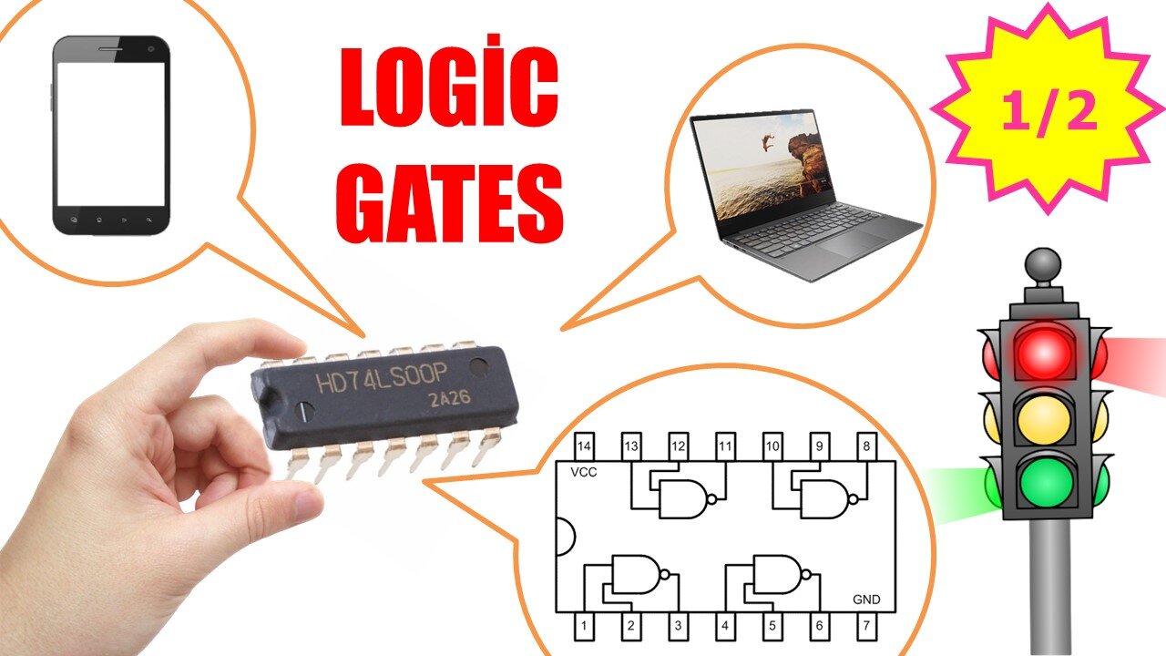
Logic Gates (AND, OR, NOT Gates) Part 1/2
In this video, I will explain the working principle of logic gates that form the basis of all electronic devices we use, which we can encounter in many areas in daily life. When we say digital electronics, the first thing that comes to our mind is logic gates. When numerical expressions are mentioned, level 1, level 0, logic circuits or in other words logic gates come to mind. This type of integrated circuit consists of circuits made with basic electronic elements such as transistors, resistors and diodes.
Logic gates form the basis of digital systems. Input information is transferred to the output by performing Boolean mathematics operations. Operations are performed on the logical expressions Logic-1 and Logic-0. The reciprocal of 1 logic expression is defined as 5V, and the reciprocal of 0 logic expression is defined as 0V.
Now let's look at how to number the pins of the logic gates. When we hold it to read the text on the IC, there is a notch on the left side. The pins are numbered starting from this notch. Logic gate ICs are generally 14 pins.
For example, when we look at the internal structure of the 7408 IC, we see that it consists of four AND gates. This logic gate has two inputs and one output. When we go into a little more detail and look inside an AND gate, we see that there is a circuit consisting of two BJT transistors and resistors.
There are 7 types of basic logic gate circuits: They are the AND gate, OR gate, NOT gate, NAND gate, NOR gate, XOR gate, and finally the XNOR gate. These circuits, also known as logic gates, produce appropriate logical results with 1 and 0 data received from the input, namely 5V and 0V, within a certain Boolean Algebra framework. That is why we can say that they are indispensable elements of digital electronic systems. Now, let's examine the symbols, mathematical expressions and truth tables of these logic gates one by one. In order for the video not to be too long and boring, I will explain the AND, OR and NOT gates in this video. In the next video, I will explain other logic gates.
00:00 Introductor
02:29 AND Gate
04:55 OR Gate
06:40 NOT Gate
#logic #gates #electronics
-
 5:24
5:24
Electrical Electronics Applications
2 years ago $0.02 earnedHow to Calculate Capacitance and Voltage Value of Capacitor?
189 -
 LIVE
LIVE
FreshandFit
7 hours agoAkaash Replies to FreshandFit w/ Girls
6,319 watching -
 LIVE
LIVE
Man in America
6 hours agoBANNED TECH: The Tesla Secrets Rockefeller Crushed to Keep You Sick w/ Linda Olsen
1,419 watching -
 LIVE
LIVE
Drew Hernandez
19 hours agoCANDACE OWENS ASSASSINATION PLOT?
997 watching -
 1:05:15
Inverted World Live
4 hours agoOne Big Happy Thanksgiving | Ep. 147
17.5K4 -
 2:44:12
TimcastIRL
3 hours agoCandace Owens OFF AIR, Warns France Trying To KILL HER, Says Feds CONFIRM RECEIPT | Timcast IRL
160K114 -
 LIVE
LIVE
SpartakusLIVE
3 hours ago#1 King of Content ARRIVES, The Masses UNDULATE with EXCITEMENT
886 watching -
 15:51
15:51
Upper Echelon Gamers
5 hours ago"INFLUENCERS" - House of LIES
104 -
 1:29:23
Glenn Greenwald
6 hours agoMarco Rubio, Europe Thwart Ukraine Peace Deal; NSA Illegally Leaks Steve Witkoff's Diplomatic Calls; Bari Weiss's Comically Out of Touch Plan for CBS | SYSTEM UPDATE #550
127K56 -
 51:15
51:15
State of the Second Podcast
7 hours agoCan You Trust Paid Gun Reviews? (ft. Tactical Advisor)
34