Premium Only Content

What is a Resistor? How does a Resistor work?
Hello friends! In this lesson, I will try to explain you the types of resistors used in almost all electrical and electronic circuits. As in other circuit devices, there are many types of resistors. We will study what these are and how they are used. The unit of the resistors are ohms and they are indicated with the letter R in the circuit. As you can see here, we can analyze the resistors in three groups: Fixed Resistors, Variable Resistors and Dependent Resistors. Variable and Dependent resistors are also available in different versions.
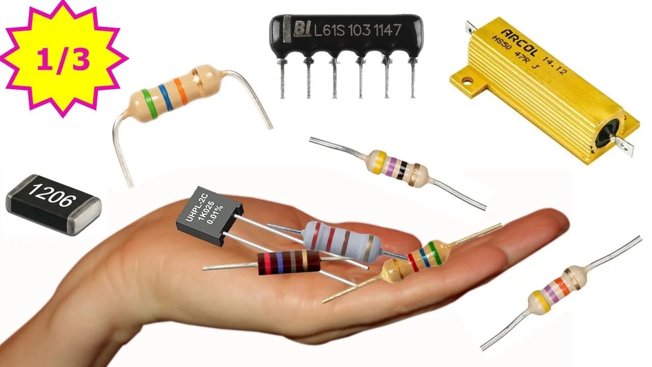
I will try to explain the types of resistors in three different videos so that the lesson gets not too long. In this lesson we will analyze Fixed resistors. Now let's take a look at the shapes, symbols, features and how they are used in the circuit. All of the resistors you see in the figure are fixed resistors. The values of these resistors do not change with environmental effects and are used to fix the circuit current at a certain value. The reason of the different structures is that the current intensity of the circuit to be used is different.
The materials used in fixed resistors differ. The value of these resistors can either be written on or understood by looking at the color codes on them. There are two types of circuit symbols used for fixed resistors. It is possible to come across the use of both of these symbols. To better understand the basic role of resistors in the circuit, we can analyze this figure. A current occurs as a result of the movement of electrons in an electrical circuit. The force that creates current by moving these electrons is voltage.
It is the resistance that limits the current by reducing the flow of electrons. There is a Current = Voltage/Resistance relationship between the three of them. If we show them in letters, I = V / R. This ratio between the three is Ohm's Law. We can show this shape as an electrical circuit. For example; take the resistance value 2.2kΩ and the voltage value 9V on this circuit. According to Ohm's Law, the current is approximately 4mA. If the resistor value increases here, the current value decreases. Because, resistance and current intensity are inversely proportional. So how to use a fixed resistor circuit, now let's look at it. Let's learn the basic usage through a simple circuit. For example, let's have a 9V voltage source. With this source, we will ensure that a LED is properly illuminated. When we connect the source directly to the LED, a current flows through the circuit and the LED gives light. However, since this current flowing through the circuit is high, the LED burns out after a short time and no current flows through the circuit.
Because, for a LED to work properly, the current that it flows on it must be between 15 and 30 mA. But if we connect the LED to this source together with a resistance of 330Ω, the LED will light for a long time without any damage. Because the current flowing through the circuit will be around 27mA. The current flowing through the circuit should be adjusted with suitable resistors in order to prevent damage to the circuit elements used. If we want to use this LED properly with 12V voltage source, this time we should use higher one such as 470Ω resistor. Thus, since a current of approximately 25mA will flow through the circuit, LED gives light for a long time without any damage. It doesn't matter if the resistance is here or there. Because, as the same current will flow through all circuit elements in series circuits, this will not change the current intensity flowing through the LED. Let's look at another example of how to use fixed resistors. Let's connect 100Ω resistor to a power source as shown here. According to the current flowing through this circuit, our lamp gives a certain amount of light. When we connect the same power source to this lamp with a resistor of 330 Ω, we can see that the brightness of the lamp is slightly reduced as less current will flow through the circuit.
When we connect a higher resistor such as 470Ω, the current will reduce even more, so the brightness of the lamp will be reduced a little more. As seen, the resistance value has determined the intensity of the current flowing through the circuit. If we increase the resistance value even more, the current flowing through the circuit will be much lower and maybe not enough for the lamp to light up. When we need higher resistors, we can connect the resistors in series. Because in series connected resistors, equivalent resistance is equal to total value of resistors.
-
 8:02
8:02
Electrical Electronics Applications
2 years ago $0.03 earnedWhat are the Types of Transistors?
1821 -
 2:03:36
FreshandFit
11 hours agoAkaash Replies to FreshandFit w/ Girls
165K16 -
 1:07:49
Man in America
10 hours agoBANNED TECH: The Tesla Secrets Rockefeller Crushed to Keep You Sick w/ Linda Olsen
26.7K7 -
 4:40:43
Drew Hernandez
23 hours agoCANDACE OWENS ASSASSINATION PLOT?
33.7K13 -
 1:05:15
Inverted World Live
8 hours agoOne Big Happy Thanksgiving | Ep. 147
76.6K5 -
 2:44:12
TimcastIRL
7 hours agoCandace Owens OFF AIR, Warns France Trying To KILL HER, Says Feds CONFIRM RECEIPT | Timcast IRL
222K179 -
 5:55:35
SpartakusLIVE
7 hours ago#1 King of Content ARRIVES, The Masses UNDULATE with EXCITEMENT
43.9K4 -
 15:51
15:51
Upper Echelon Gamers
9 hours ago $5.93 earned"INFLUENCERS" - House of LIES
22.8K3 -
 1:29:23
Glenn Greenwald
10 hours agoMarco Rubio, Europe Thwart Ukraine Peace Deal; NSA Illegally Leaks Steve Witkoff's Diplomatic Calls; Bari Weiss's Comically Out of Touch Plan for CBS | SYSTEM UPDATE #550
155K96 -
 51:15
51:15
State of the Second Podcast
12 hours agoCan You Trust Paid Gun Reviews? (ft. Tactical Advisor)
50.7K4