Jeffrey Henderson | My Custom TIG/MIG Weld Weaver | Oscillator System | Automated Welding Process
Hi Everyone,
I’m back 😊.
A friend of mine purchased a brand-new automated rotary welding machine that exploded and engulfed in smoke when he turned it on. The defective machine can be seen in the supplementary design and manufacturing part once the video samples/clips are completed at the very beginning of the section (Repairs were performed to the faulty power supply, damaged by the inexpensive male/female connectors that are clearly not rated for high DC currents/voltages).
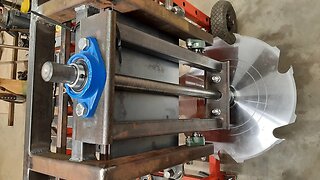
After I repaired the machine (its electronics/controls), he requested if I could come up with something/build a device that could replace the bracket and generate a controllable oscillating motion, to which any welding torch (MIG/TIG) could be connected. He also requested if I could leave the width of the weld bead adjustable and the speed of the oscillation to be changeable to suit his needs for various work pieces. So, the next day I had it in my head on what tasks needed completed before I started putting something together that worked. I first removed a wiper mechanism from an old Honda Accord car and started from there.
The proposed portable welding manipulator could be employed in automated welding applications where precision and efficiency are required. The primary driving considerations for this bespoke device seen in the video are weld torch/boom stiffness, welding head/torch stability, operator controls, and ease of use. The gadget is specifically intended to reduce welding operator fatigue and improve production quality and productivity.
The last image in the supplementary design and manufacturing section are his workpieces that were welded in large quantities using a considerably coarser SIP transformer type welder than my MIG welder in the clips, demonstrating the significance of oscillation.
In general, the bespoke device now works with the rotating table to produce a complete welding manipulator system that is important for applications involving pipes and vessels, as it maximises productivity and efficiency.
Furthermore, the more exact the equipment is, the less scrap there would be, and the results aren't skilled predictable because the entire process is automated at the push of two buttons once set up, as demonstrated in the video clips. Due to the accuracy of the oscillating mechanism, the system does not require laser vision tracking to follow the weld gap.
The oscillating device is used to enhance the region where the weld penetrates. Lack of fusion; lack of or partial penetration; fractures; porosity; inappropriate weld form and size can all result from insufficient welds or with the usage of stringers at a flange type connection. Multiple settings can now be adjusted using the new gadget installed to the rotary machine. It is critical for the user to position the centre of the weave's stroke towards the centre of the weld gap with respect to the thickness of both the flange and pipe gauge. A mismatch in this case cannot be tracked by the system. However, preliminary runs/tests can be altered by the user while keeping an eye on the first test pieces. This results in welds of higher quality that are always in the right place.
The weaver control module (PWM controller) provides weave motion to the prefabricated weave drive system via mechanical linkages and the DC car wiper motor, resulting in welds ranging in width from 4mm to 10mm.
An increase in current load on the LCD display indicates that there is extra demand on the PWM controller which would result in a fault etc., worn bearings/linkages.
The bearing hub was designed in two variations. Due to insufficient tolerance, the 25mm shaft and bushings (seen in the supplementary design and manufacturing section) was scrapped as there was too much head play at the torch in run state. As a result, the final mechanism was built utilising a bicycle pedal hub that housed two roller bearings. This was a huge benefit because any play in the assembly could be removed by simply tightening a large flange nut on one side of the hub. All the links were also custom fabricated by welding them together from scrap metal and shaping them using the available lathe machine and hand tools.
A bicycle seat’s notched, pivoting/adjustable bracket was also taking advantage of as I could achieve 3-axis of movement for the head torch. This was a smart move to benefit flexibility, usability, accuracy and increase precision of the weld positions. A custom stainless enclosure was created to hold the PWM controller which is mounted to the DC wiper motor.
Finally, a power supply was placed in a large enclosure to protect it from splatter, dust, and moisture.
I hope everyone enjoys the detailed video as much as I enjoyed creating this simple but efficient way of weaving welds precisely.
Thank you for watching.
Jeffrey
-
 1:36:18
JeffreyMaster
7 months ago $0.01 earnedJeffrey Henderson | DIY Miniature Wire Spot Welder | Precision Wire Frame Modelling System | Part 2
6641 -
 1:11:55
JeffreyMaster
8 months ago $0.02 earnedJeffrey Henderson | DIY Miniature Wire Spot Welder | Precision Wire Frame Modelling System | Part 1
270 -
 6:53
6:53
Peter von Panda
4 years agoWEN 2305 Rotary Tool Kit Review
120 -
 1:32
1:32
wavelanka
3 years agoSmart Motion Control Electric Screwdriver | World Top New Technologies | we love technology
82 -
 17:40
17:40
Donn DIY
6 years agoSaw Head Lifting System - Band Sawmill Build #15
7 -
 19:32
19:32
Electrician U
1 year agoAll the Tools Apprentice Electricians ABSOLUTELY Need!
1541 -
 59:27
59:27
Keith Fenner, Career, Hobbies and Life
1 year ago $0.12 earnedJob Shop Tooling Made On My WAZER Water Jet Machine
1862 -
 24:01
24:01
Donn DIY
1 year agoSwingblade SAWMILL Build Ep.2 - Saw Carriage Fabrication
4241 -
 7:56
7:56
4DIYers
8 months agoWrenches 101: Here's What you Need to Know
17 -
 0:41
0:41
Spencer Does Reviews
10 months agoUnboxing | Vtopmart 20 Oscillating Quick Release Saw Blades
6