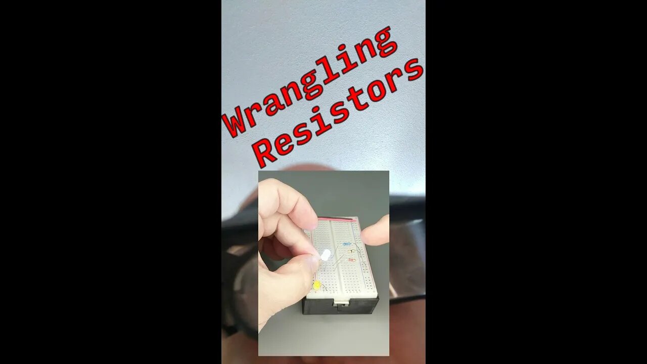
Wrangling Resistors: Creating a Calibrated LED Light for Photoresistor Testing
Wherein we discuss making a calibrated LED light pen that can be used to figure out what bias resistors to use for each sensor of the EUP5108 Punch Card Reader.
Breadboard battery box: https://www.thingiverse.com/thing:3855654
Cold solder breadboard: https://www.thingiverse.com/thing:3834264
This circuit on TinkerCad WAS the basis of the physical design but as we shall see few simulations stand up to variability of actual electronic hardware.
https://www.tinkercad.com/things/d9uO3r4u5sQ-bizpunchcardreader
We (thought we) learned last time that the light sensors (photo resistors) would best be read using the Analog inputs - in practice we just dropped the LEDs for each bit and used the digital inputs as originally planned - but some sensors were way more sensitive than others so reading the card data was unreliable.
Still to do: Showing how I connected the sensor bar to an Arduino nano microcontroller along with the code used to read the punch card data into the computer.
Please consider supporting the channel on Patreon:
https://www.patreon.com/eunumpluribus
Or
Send us a tip with Bitcoin: 17KYzdgkefseqiCcPHxDbusfyjWdBgXTS1
~~~~~~~~~~~~~~~~~~~~~~~~~~~~~~~~~~~~~~~~~~~
YouTube: https://tinyurl.com/rop59h3
TinkerCAD: https://tinyurl.com/wpug34w
Thingiverse: https://tinyurl.com/w96nz2k
Linkedin: https://tinyurl.com/u9r9qjm
~~~~~~~~~~~~~~~~~~~~~~~~~~~~~~~~~~~~~~~~~~~
Please subscribe to my channel…it REALLY helps.Like my video? Hate my video? Let me know, VOTE! Please leave a comment, let me know how I'm doing.
#shorts #electronics #computing #programming #8bit
-
 29:15
29:15
BlabberingCollector
2 days agoHarry Potter X Fortnite, Fans Reee Over Trans Rights, NEW Audiobooks Are OUT, Wizarding Quick Hits
31.6K4 -
 1:20:42
The Connect: With Johnny Mitchell
6 days ago $13.66 earnedThe Truth Behind The U.S. Invasion Of Venezuela: Ed Calderon Exposes American Regime Change Secrets
39.7K25 -
 2:10:18
FreshandFit
7 hours agoAfter Hours w/ Girls
136K36 -
 2:06:29
TimcastIRL
13 hours agoAirlines Cancel Over 700 Flights, Travel APOCALYPSE Is Now, Trump Says END FILIBUSTER | Timcast IRL
236K120 -
 9:02:44
SpartakusLIVE
18 hours agoTOXIC Solos on ARC Raiders || Friday Night HYPE - WZ or Redsec Later?
78.6K2 -
 2:15:42
TheSaltyCracker
11 hours agoWoke is DEAD ReeEEStream 11-07-25
128K222 -
 1:29:13
Sarah Westall
10 hours agoThe City of London: Infiltration, Intimidation & Centralized Power w/ Mike Harris
52.5K15 -
 10:14:18
Dr Disrespect
20 hours ago🔴LIVE - DR DISRESPECT - ARC RAIDERS - AGAINST ALL DANGER
203K26 -
 32:09
32:09
ThisIsDeLaCruz
1 day ago $6.52 earnedFalling In Reverse: Christian Thompson’s Stage Tech Revealed
45K8 -
 4:41:02
SynthTrax & DJ Cheezus Livestreams
1 day agoFriday Night Synthwave 80s 90s Electronica and more DJ MIX Livestream 80s Night / Late Night Nostalgia
52.8K9