PLC Ladder Logic Basics for Beginners Box Sorting Conveyor Using Studio 5000
PLC Ladder Logic Basics For Beginners: Box Sorting Conveyor Using Studio 5000 Version 35
Programmable Logic Controllers (PLCs) are computer-based systems that are widely used in industrial automation to control machines and processes. One of the primary languages used to program PLCs is ladder logic, which is a graphical programming language that resembles the rungs of a ladder. In this article, we will cover the basics of ladder logic programming and demonstrate how to create a simple box sorting conveyor system using Studio 5000 version 35, a software platform for programming and configuring Allen-Bradley PLCs.
Before we dive into the specifics of ladder logic programming, let's first define some key terms and concepts that are essential for understanding how PLCs work.
1. Inputs: These are signals that are received by the PLC from external devices such as sensors, switches, and other control devices.
2. Outputs: These are signals that are sent by the PLC to external devices such as motors, actuators, and other control devices.
3. Ladder logic diagram: This is a graphical representation of the logical relationships between inputs and outputs in a PLC program. It is made up of rungs, which are horizontal lines that represent the steps in the logic, and contacts and coils, which are vertical lines that represent the conditions and actions of the logic.
4. Contacts: These are symbols that represent the state of an input or output. Normally open (NO) contacts are used to represent an input that is not active, and normally closed (NC) contacts are used to represent an input that is active.
5. Coils: These are symbols that represent the state of the output. An energized coil represents an output that is active, and a de-energized coil represents an output that is not active.
Now that we have a basic understanding of PLCs and ladder logic, let's move on to creating a simple box-sorting conveyor system using Studio 5000.
1. First, open Studio 5000 and create a new project by selecting "File - New - Project."
2. Next, add a new PLC by selecting "Project - Add New PLC."
3. In the "PLC Configuration" window, select the type of PLC you are using and click "OK."
4. To create the ladder logic diagram, select the "Ladder Diagram" tab in the main window and then click the "Add New Rung" button.
5. To add inputs and outputs to the ladder logic diagram, select the "I/O Configuration" tab in the main window and then click the "Add New I/O" button.
6. To add a box sensor to the ladder logic diagram, drag and drop a "Normally Open Contact" from the "Contacts" palette onto the first rung of the ladder logic diagram. Then, assign this contact to the input for the box sensor by double-clicking the contact and selecting the appropriate input from the "I/O Configuration" tab.
7. To add a box actuator to the ladder logic diagram, drag and drop a "Coil" from the "Coils" palette onto the first rung of the ladder logic diagram. Then, assign this coil to the output for the box actuator by double-clicking the coil and selecting the appropriate output from the "I/O Configuration" tab.
8. To add logic to the ladder logic diagram, you can use various logical operators such as AND, OR, and NOT. For example, if you want the box actuator to activate only when needed.
0:00 Intro
0:35 Explaining the Ladder Logic
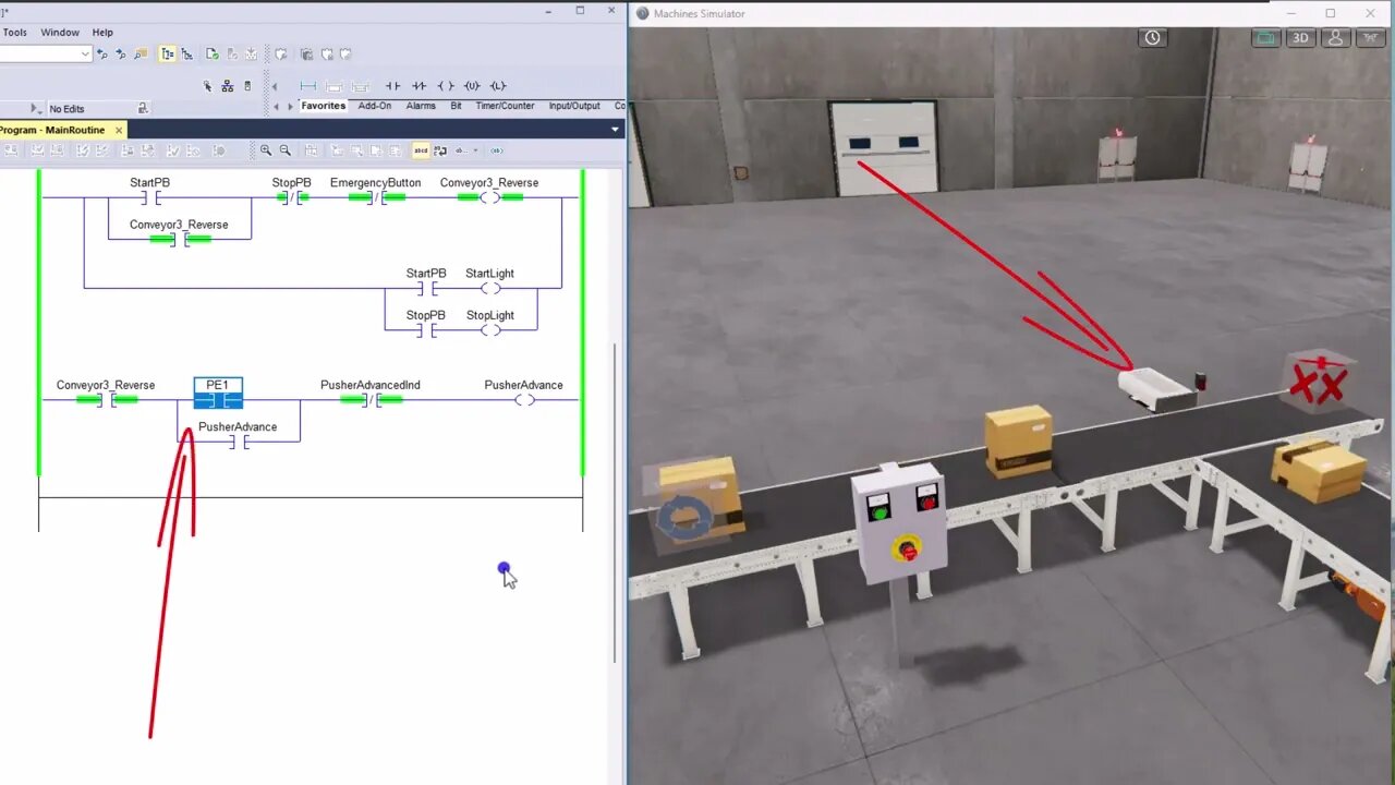
1:15 Conveyor Seal in Logic
1:45 Box Pusher Logic
2:10 Running the System to Watch The Ladder Logic
2:50 Ladder Instructions that were used
4:00 Pusher Seal in Logic
5:00 Important Note for the future
Thank you for watching the video.
Learn, Implement, Succeed
Visit:
https://www.allen-bradley-plc-training.com/
Other social media:
LinkedIn: https://www.linkedin.com/in/shane-welcher-sr/
Facebook: https://www.facebook.com/OnlinePLCSupport
#LadderLogicBasics #LadderLogicBeginners #ladderlogic
-
 5:21
5:21
Shane Welcher
1 year ago $0.02 earnedRockwell Automation's Studio 5000 V30 Servo Motion Group Not Synced
97 -
 LIVE
LIVE
The Mel K Show
1 hour agoA Republic if You Can Keep It-Americans Must Choose 11-04-25
89 watching -
 UPCOMING
Grant Stinchfield
22 minutes agoThe Mind Meltdown: Are COVID Shots Fueling America’s Cognitive Collapse?
-
 1:00:46
VINCE
3 hours agoThe Proof Is In The Emails | Episode 161 - 11/04/25
117K85 -
 LIVE
LIVE
Benny Johnson
2 hours ago🚨Trump Releases ALL Evidence Against James Comey in Nuclear Legal BOMBSHELL! It's DARK, US in SHOCK
5,810 watching -
 LIVE
LIVE
Badlands Media
10 hours agoBadlands Daily: November 4, 2025
3,432 watching -

Wendy Bell Radio
7 hours agoBUSTED.
48.9K74 -
 LIVE
LIVE
The Big Mig™
3 hours agoDing Dong The Wicked Witch Pelosi Is Gone
32 watching -
 DVR
DVR
Daniel Davis Deep Dive
2 hours agoFast Tracking Weapons to Ukraine, Close to $3 Billion /Lt Col Daniel Davis
6.12K6 -
 LIVE
LIVE
The State of Freedom
4 hours ago#347 Relentlessly Pursuing Truth, Transparency & Election Integrity w/ Holly Kesler
18 watching