PLC Ladder Logic Basics For Beginners With A Working Conveyor
Ladder logic is a programming language used in industrial automation systems, such as those found in manufacturing plants. It is a graphical representation of a program, with symbols and lines representing logical statements and actions. Allen-Bradley is a brand of programmable logic controllers (PLCs) that uses ladder logic to control industrial processes.
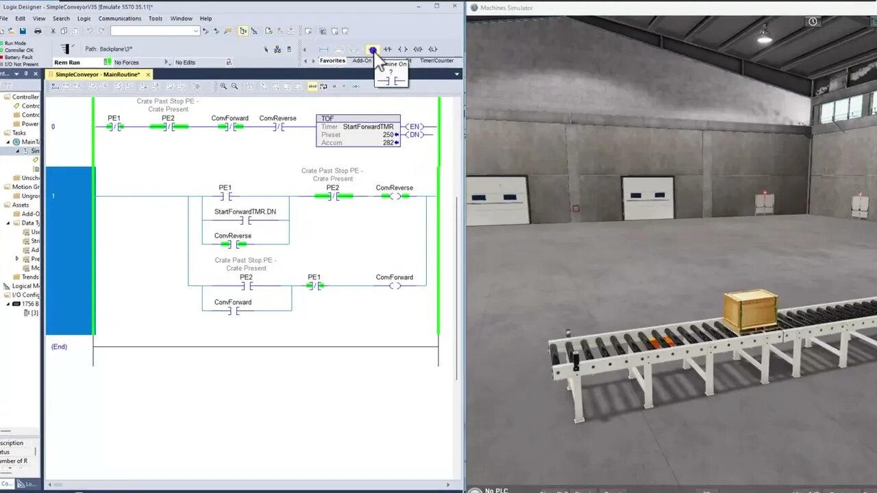
For beginners learning ladder logic, a good starting point is understanding how it is used to control a conveyor system. A conveyor system consists of a series of rollers or belts that move materials from one location to another. It is commonly used in manufacturing and material handling applications.
To control a conveyor system using ladder logic, we need to first understand the inputs and outputs of the system. Inputs are signals that are received by the PLC, such as button presses or sensor readings. Outputs are signals that are sent by the PLC, such as turning on a motor or activating a solenoid valve.
Next, we need to determine the logic of the system. For example, if we want the conveyor to start when a button is pressed and stop when a sensor detects an object, we would create a ladder logic program that reads the button press input and the sensor input. If the button is pressed and the sensor is not detecting an object, the program will send an output signal to start the conveyor. If the sensor detects an object, the program will send an output signal to stop the conveyor.
To create the ladder logic program, we use symbols and lines to represent the inputs, outputs, and logic of the system. A common symbol for an input is a square, and a common symbol for an output is a circle. Lines are used to connect the symbols and represent the logic of the program.
Here is an example of a simple ladder logic program for a conveyor system:
[Input] [Output]
[Button]--[Conveyor]
[Sensor]--[Stop]
In this program, the input symbol on the left represents the button press, and the output symbol on the right represents the conveyor motor. The line connecting the two represents the logic that if the button is pressed, the conveyor will start. The input symbol below the button represents the sensor, and the output symbol below the conveyor represents the stop signal. The line connecting the two represents the logic that if the sensor detects an object, the conveyor will stop.
Ladder logic can become more complex as the system becomes more sophisticated, but this basic example illustrates the concept of using inputs, outputs, and logic to control a conveyor system using Allen-Bradley PLCs and ladder logic. With practice and a thorough understanding of the principles of ladder logic, beginners can confidently control and automate industrial processes using this powerful programming language.
Thank you for watching the video.
Learn, Implement, Succeed
Visit:
https://www.allen-bradley-plc-training.com/
Other social media:
LinkedIn: https://www.linkedin.com/in/shane-welcher-sr/
Facebook: https://www.facebook.com/OnlinePLCSupport
#LadderLogicBasics #LadderLogicBeginners #ladderlogic
-
 7:41
7:41
Shane Welcher
2 years agoScaling a PIDE Output for a 4 to 20MA signal
54 -
 1:54:42
The Quartering
3 hours agoFood Stamp Riots Are Coming, New Charlie Kirk Assassin Discord Messages Leak & Console Wars End!
133K48 -
 16:09
16:09
iCkEdMeL
3 hours ago $4.69 earned🔴 LIVE: Tyler Robinson Pretrial Hearing in Charlie Kirk Assassination Case
15.8K3 -
 1:11:50
DeVory Darkins
4 hours agoDemocrats left scrambling after USDA issues NIGHTMARE Update
161K132 -
 21:05
21:05
Stephen Gardner
4 hours ago🔥Trump Drops NIGHTMARE NEWS for Democrats!!!
38.6K114 -
 LIVE
LIVE
Owen Shroyer
2 hours agoOwen Report - 10-27-2025 - Trump Secures Trade Deals Ahead Of Meeting With Xi
1,232 watching -
![[Ep 778] NYC Embraces Communism, Argentina Rejects It | Newsom Lies; As Always](https://1a-1791.com/video/fwe2/34/s8/1/w/y/k/u/wykuz.0kob-small-Ep-778-NYC-Embraces-Communi.jpg) LIVE
LIVE
The Nunn Report - w/ Dan Nunn
2 hours ago[Ep 778] NYC Embraces Communism, Argentina Rejects It | Newsom Lies; As Always
155 watching -
 1:09:36
Sean Unpaved
5 hours agoBrian Kelly's Boot From LSU, NFL Week 8 Snoozefest, & CFB's Week 9 Upset Rodeo
28.6K2 -
 1:04:35
Jeff Ahern
2 hours ago $1.84 earnedMonday Madness with Jeff Ahern
14.3K1 -
 1:03:58
Timcast
5 hours agoTrump DEPLOYS Election Monitors To Blue States, Democrats SCREAM RIGGED ELECTION
188K153