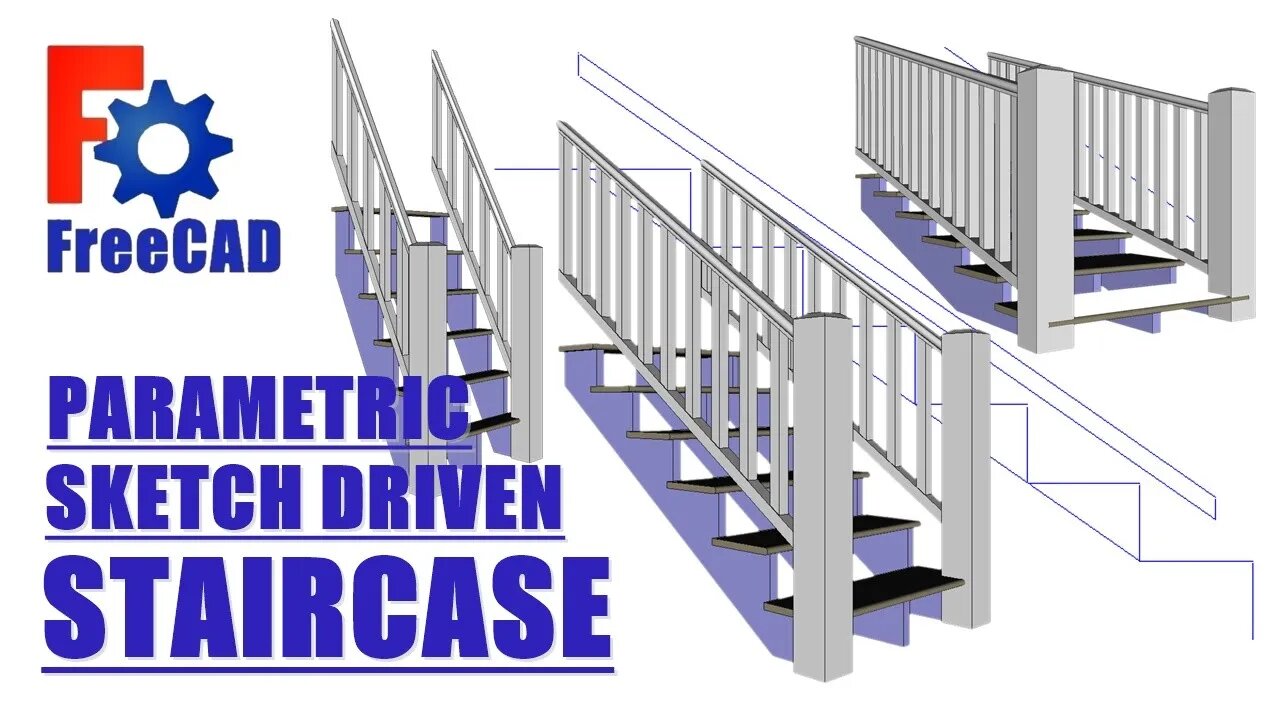
FreeCAD: Parametric sketch driven Staircase
Mostly parametric, less the number of steps, still thinking about that.
The driving sketch:
1. Contains only essential geometry and datum points.
2. When dragging sketches out their bodies, only link essential geometry with external geometry command. Create the rest of the sketches inside the body.
3. After the drive sketch is complete and bodies attached to it, it CANNOT be changed. The naming problem will cause things to jump around.
4. Constrain sketches in a way in which the constraint cannot flip over, using center points usually fixes that.
5. A stair sketch can be driven by overall height and run, or rise & run of each step.
6. Sketch geometry from another body can also be referenced by CarbonCopy + Ctrl, but that command converts the entire sketch, but would be possible to use by changing some lines to construction lines.
Stair design for a CAD model:
1. The Run: Start with run that is 1" -1.5" (nose and possible riser) less than the most common tread (11.5" in the US, 10.5" in Canada, deck boards are 5.5" x 2 + 1/8" = 11.125")
2. The Rise and number of steps: Divide the total height (finished floor to finished floor) by a number that results in a step rise of 7-8", it's better to land on an 1/16" or more.
3. Remember the first step of the cut stringer is 1 tread thickness less than the rest of the of the cut steps.
4.The railing: spindles no more than 4" apart, 2 spindles per step (no bottom rail ) works with certain geometry. Don't make railing sections to long, and small supports under sections is a good idea.
If you liked the video hit the thumbs up.
Thanks for watching.
-
 8:26
8:26
Hollywood Exposed
16 hours agoKid Rock LEAVES Bill Maher Scrambling After Trump Debate Gets Messy
13.2K11 -

BEK TV
3 days agoTrent Loos in the Morning - 11/17/2025
11K2 -
 9:25
9:25
MattMorseTV
16 hours ago $47.55 earnedTrump’s GAMBLE just PAID OFF… BIG TIME.
59.2K100 -
 18:03
18:03
Nikko Ortiz
21 hours agoNikko Ortiz Night Routine...
111K19 -
 LIVE
LIVE
FyrBorne
12 hours ago🔴Battlefield REDSEC Live M&K Gameplay: Pyro+ Games
151 watching -
 LIVE
LIVE
Lofi Girl
3 years agolofi hip hop radio 📚 - beats to relax/study to
361 watching -
 2:12:56
BBQPenguin_
4 hours agoEscape From Tarkov 1.0 Wipe! New Story & Full Release!
6.69K -
 1:48:07
Midnight In The Mountains™
2 hours agoMorning Coffee w/ Midnight & The Early Birds of Rumble
5.43K2 -
 24:21
24:21
a12cat34dog
1 day agoGUITAR HERO AT DREAMHACK | HALLOWEEN 2025
22.8K11 -
 4:14:04
B2ZGaming
10 hours agoB2Z.... Assemble! | B2Z Gaming
5.35K