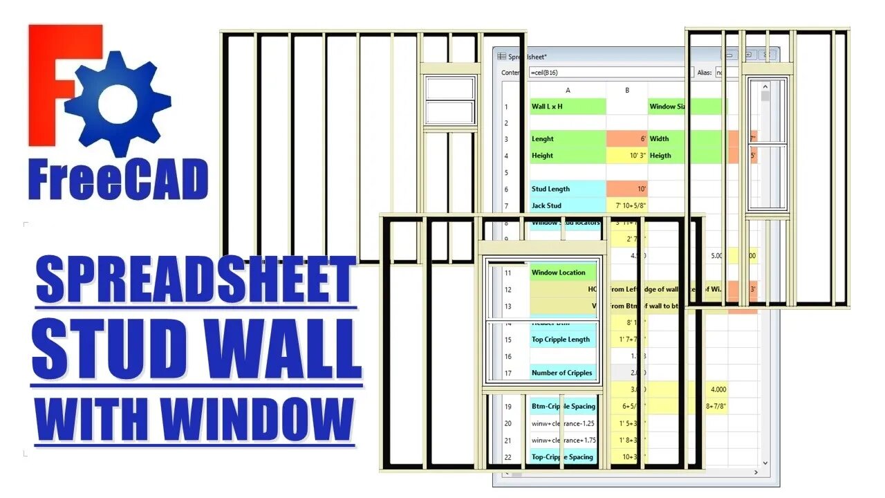
FreeCAD: Stud Wall with Window spreadsheet
Creating a parametric spreadsheet driven stud wall with window.
The Stud Wall with window assembly.
(I create this prior to inserting spreadsheet)
1. In PartDesign WB (or your choice), create bottom & top plates and one starter stud and one end stud. Create these bodies with the same origin and transform them into position.
2. From the Draft WB: use array command to create stud array. Ok anything in the dialogue box, and fix the array from the properties panel, with 16" spacing.
3.From the BIM WB: create a window. If the dialogue box doesn't create what you want, it can be fixed from the sketch.
4. Edit the window sketch: delete constraint off the origin point, drag sketch away from origin. Create a point on the center of the bottom line of the window sketch (symmetry command). Create a vertical and horizontal dimension from the origin to the point just created, these are the window location dimensions.
5. Hide any stud that touches the window. Copy and paste four studs and four bottom plates. Transform and re-dimensions these bodies into: 2 window studs, 2 jack studs, 2 headers and 2 sill plates. Create one top and bottom cripple. Always create bodies from the same assembly origin and transform into position. This is the rough window opening, it will all be located relative to the window location point.
We now have 2 datum points in this assembly. The assembly origin and the window location point. Everything in the assembly is located relative to one or both of these two points.
The Spreadsheet
1. From the Spreadsheet WB: create a new spreadsheet.
2. Name of all the bodies and dimensions that need to be controlled.
Wall LxH, Window LxH, Window location, stud length, stud spacing, sill width, header width, jack stud length, bottom & top cripple lengths, etc..
3. Of all the features controlled by the spreadsheet, only 6 are meant to be given entries/variables: Wall LxW, Window LxW and Window WxH.
4. Create and enter in all the equations to locate bodies: Wall H= stud length +3", sill W= window width + .25", etc...
5. Add all aliases to cells, keep names short, wall length: wl, window width: winw, window location vertical: winlv, etc...
6. Move through the assembly replacing dimensions with spreadsheet aliases (or equations) via the properties panel, click silver button. type sp in the dialogue box, hit down arrow, hit enter, type appropriate alias, hit enter, it will turn blue when link is created.
IMPORTANT: FreeCAD spreadsheet uses Python functions, NOT Excel. But some functions are the same.
Python function for rounding up is: ceil()
7. When creating number of studs and number of cripples. This number can NOT be a fraction or decimal. This is the trick of this assembly.
x number of studs = wall length / 16"
rounding up to make whole integer = ceil(x)
8. Creating the cripple arrays: The cripple spacing is different top and bottom because the header is 3" wider than the sill, so two arrays are required, but only one value changes in these two equations.
I know I blasted through this quickly, and skipped a lot and no dialogue. But this for intermediate to advanced people.
Cripple spacing: puzzled solved! (mathcodeprint ;-) )
If you got anything out of it, hit the thumbs up.
Cheers.
-
 LIVE
LIVE
DLDAfterDark
3 hours ago $0.05 earnedDLD Live! Feat. Red Dawn Readiness! Glock FRT's - Striker Fire Safety Concerns - ACE Trigger
225 watching -
 LIVE
LIVE
BlackDiamondGunsandGear
2 hours agoAre ALL Striker Fired Pistols UNSAFE? // After Hours Armory
852 watching -
 LIVE
LIVE
SpartakusLIVE
7 hours ago#1 Saturday Spartoons on RUMBLE PREMIUM
3,381 watching -
 1:04:59
Man in America
7 hours ago“Summoning the Demon” — The AI Agenda Is FAR WORSE Than We Know w/ Kay Rubacek
26.8K19 -
 2:16:48
Tundra Tactical
5 hours ago $0.06 earned🎯💥 The World’s Okayest Gun Show 🔫😂 | LIVE Tonight on Rumble!
10.4K -
 3:36:03
Mally_Mouse
1 day ago🌶️ 🥵Spicy BITE Saturday!! 🥵🌶️- Let's Play: Tower Unite!
30.1K1 -
 58:59
58:59
MattMorseTV
5 hours ago $1.12 earned🔴Trump just BROKE Newsom.🔴
49.3K57 -
 18:14
18:14
Her Patriot Voice
6 hours agoWho Is WORSE for NYC: Trump Girl or Socialist?
32K23 -
 3:39:42
SavageJayGatsby
5 hours agoSpicy Saturday with Mally! | Road to 100 | $300 Weekly Goal for Spicy Bites!
31.3K1 -
 LIVE
LIVE
FomoTV
7 hours ago🚨 Swamp Theater: FBI Raids Bolton 🕵 Still NO Epstein Files, Trump's Troops & the Red Heifer Hoax 🐂 | Fomocast 08.23.25
52 watching