
Pelouze / Rubbermaid / Dymo model 4010 Scale Repair
Repairing a dodgy "On" button on the Pelouze 4010 digital scale.
This scale consists of a separate weighing platform and a remote LCD display. It can be powered by a 9V battery or a 9VDC power jack. Since it's set up to auto power off to conserve the battery, the ON button gets used a lot. Over time, that button became harder to actuate to the point I couldn't turn the scale on.
The display PCB uses tactile dome switches that are pressed by little plastic pins on flexible parts of the cover. Those pins only press in the center of the metal dome and it seems that point under the dome is no longer making contact. So the fix was to enlarge the area of the pin to press on a larger portion of the dome. Also, added a bit of height to the support tower on the back side of the case to prevent the PCB from flexing.
Not sure which is the main company, if anyone knows the back story, post up in the comment section below. There are identical scales out there with Pelouze, Rubbermaid and even Dymo by Pelouze branding:
https://www.rubbermaidcommercialproducts.com/foodservice/rubbermaid-scales-and-thermometers/
Then, if that's not confusing enough, the display (and perhaps the weighing platform) seems to be manufactured by Healthometer, Inc:
https://www.healthometer.com/
The final units are then branded with custom graphics on the face of the display.
More to come...
Subscribe for more content like this
Comment, like, share & click the bell icon
And as always, thanks for watching
Intro/Outro:
Louisiana Fairytale by Austin Rogers
https://web.archive.org/web/20170402222425/http://drfiddle.com/show_tune.php?id=94
#repair #pelouze #scale
6
views

12V LED Trouble Light, PCB Details
Opening up this 12V trouble light confirmed my suspicions about the internal design. It seems the double sided printed circuit board is overly complicated for the actual circuit. This could have easily been done on a single sided board, 12V trace down one side, 0V trace down the other and then groups of 3 LEDs in series connecting those traces.
It appears that this product was made up of repurposed components. The hard wired power supply had a label indicating it originally had a coax power plug. The circuit board in the light itself seems to be over complex and had nothing in the way of current or voltage regulation. All if had was an on/off push button switch and 60 LEDs wired as 20 strings of 3 in series. I couldn't see that detail from the exterior as there was a paper label inside the tube covering the back side of the PCB.
The original 12V trouble light was purchased around 2005 from Grizzly.com. It came with a hard wired 12V power supply. I figured I could replace that with a lighter plug and use it in the truck. While that did work for a while, it became apparent that the power supply must have had current regulation to keep from over driving the LEDs. As a result, most of the LEDs burned out.
More to come...
Subscribe for more content like this
Comment, like, share & click the bell icon
And as always, thanks for watching
Intro/Outro:
Louisiana Fairytale by Austin Rogers
https://web.archive.org/web/20170402222425/http://drfiddle.com/show_tune.php?id=94
4
views
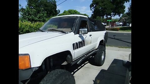
House Battery and Solar for the 4Runner - Assembled
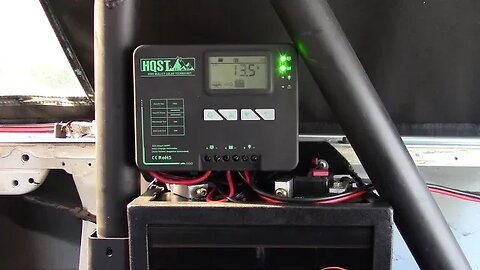
1st generation Toyota 4Runner, upgrading the power system in the rear of the truck with a 100AH LiFePO4 battery, 20 amp charge controller and 200W solar panel.
With the battery and charge controller installed, I found I didn't have as much vertical clearance as I originally planned. I think this was mainly due to not accounting for the thickness of the steel angle and clearance for the battery in the cage. Had to shrink my battery connections down in height and allow for more rotation to put them in the best orientation. I wanted the circuit breaker to be attached directly to the positive battery terminal for safety. The battery does have a 100A BMS inside that'll cut off above 100A.
I've already re-routed the PV and DC load cables out the back instead of to the side like I had them in the video. Will also shorten the battery cables and I may actually eliminate the extended connection off the breaker and just pre-wire in the positive battery cable to clean up the wiring and also to better protect that wire by putting it as far back as possible.
All the pieces of angle were cut to fit around the battery with 45* cuts on the top and bottom trays and straight 90* cuts for the rest. I used some 1/8"x1" flat bar for the back bottom and sides (so the battery could slide in). The top was a piece of 1/8" x 2" flat bar. I cut clearance notches in that bar to allow the battery terminals to fit under as well as some notches on the upper angle to clear those terminals as well. You can find that sort off steel at most hardware stores or from a supplier like McMaster-Carr or Metal Supermarkets. This is similar to the cage I built to hold my dual batteries many years ago. I welded that cage up at my evening welding class.
This whole cage is designed to fit entirely on top of the wheel well and inside the opening in the factory roll bar. This will keep these components safely out of the way of things moving around in the bed while traversing bumpy 4WD trails and washboard roads. In the past, I used to bring my Harbor Freight jump start pack and always had trouble securing it in back. This new house battery will not be moving anywhere!
Why this charge controller? A few reasons, main one was the size, it fit in the space available. The other reasons were it had a decent feature set, MPPT, 20 amp rating to handle the 200W panel, Lithium and User charging profiles, built-in BlueTooth. HoboTech did a good review on these: https://youtu.be/HySgUYqjmo8?si=QcVw6jD4AhfpRae1
Why not use a commercial "solar generator"? Two main reasons, main one is that I couldn't find anything that would fit the space I had. Second reason was reliability, I have no experience with those systems but it seems that if one part goes out, the whole unit is dead. With the setup I've designed, if the LiFePO4 battery or BMS quits, I can reconfigure the charge controller to use the lead acid batteries. If the charge controller quits, I can use the alternator to charge the LiFePO4 battery, but this will always be in parallel with 1 or both lead acid batteries. I'll run some tests later to determine if a DC-DC charger will be needed for this of it my high output Premier Power Welder alternator can handle this task. When I'm 100 miles from nowhere and something quits, I like to have options to work around the failed item.
Following videos will get into the roof top solar panel mount...
List of parts used:
LiTime Mini 100AH battery:
https://www.litime.com/products/litime-12v-100ah-mini-lifepo4-lithium-battery-upgraded-100a-bms-max-1280wh-energy
https://amzn.to/3QmxcC5
HQST 20A MPPT Charge Controller
https://hqst.refr.cc/rogerb
https://amzn.to/3S5zhnf
200W AllPowers flexible solar panel:
https://amzn.to/46z7Eax
SAE Extension cable, used 3 ft. and 6 ft. cables:
https://amzn.to/46VnLix
SAE bulkhead connector:
https://amzn.to/3tuP7h1
8 circuit power distribution block:
https://amzn.to/45Ia9pL
#4Runner #softtop #lithiumbatteries #solarpanel #chargecontroller #LiTimestory
65
views
2
comments
House Battery and Solar for the 4Runner - Adding the Charge Controller
1st generation Toyota 4Runner, upgrading the power system in the rear of the truck with a 100AH LiFePO4 battery, 20 amp charge controller and 200W solar panel.
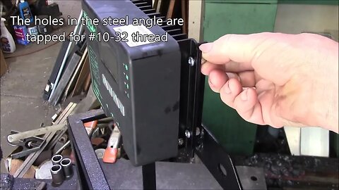
Building a cage to hold the 20 amp HQST charge controller above the battery up against the side of the bed in the 4Runner. You can see how tight this space is. The charge controller is supported by a pair of 3/4" steel angle (1/8" wall thickness) pieces with tapped holes for #10-32 machine screws and lock nuts.
All the pieces of angle were cut to fit around the battery with 45* cuts on the top and bottom trays and straight 90* cuts for the rest. I used some 1/8"x1" flat bar for the back bottom and sides (so the battery could slide in). The top was a piece of 1/8" x 2" flat bar. I cut clearance notches in that bar to allow the battery terminals to fit under as well as some notches on the upper angle to clear those terminals as well. You can find that sort off steel at most hardware stores or from a supplier like McMaster-Carr or Metal Supermarkets. This is similar to the cage I built to hold my dual batteries many years ago. I welded that cage up at my evening welding class.
This whole cage is designed to fit entirely on top of the wheel well and inside the opening in the factory roll bar. This will keep these components safely out of the way of things moving around in the bed while traversing bumpy 4WD trails and washboard roads. In the past, I used to bring my Harbor Freight jump start pack and always had trouble securing it in back. This new house battery will not be moving anywhere!
Why this charge controller? A few reasons, main one was the size, it fit in the space available. The other reasons were it had a decent feature set, MPPT, 20 amp rating to handle the 200W panel, Lithium and User charging profiles, built-in BlueTooth. HoboTech did a good review on these: https://youtu.be/HySgUYqjmo8?si=QcVw6jD4AhfpRae1
Why not use a commercial "solar generator"? Two main reasons, main one is that I couldn't find anything that would fit the space I had. Second reason was reliability, I have no experience with those systems but it seems that if one part goes out, the whole unit is dead. With the setup I've designed, if the LiFePO4 battery or BMS quits, I can reconfigure the charge controller to use the lead acid batteries. If the charge controller quits, I can use the alternator to charge the LiFePO4 battery. I'll run some tests later to determine if a DC-DC charger will be needed for this of it my high output Premier Power Welder alternator can handle this task. When I'm 100 miles from nowhere and something quits, I like to have options to work around the failed item.
List of parts used:
LiTime Mini 100AH battery:
https://www.litime.com/products/litime-12v-100ah-mini-lifepo4-lithium-battery-upgraded-100a-bms-max-1280wh-energy
https://amzn.to/3QmxcC5
HQST 20A MPPT Charge Controller
https://hqst.refr.cc/rogerb
https://amzn.to/3S5zhnf
200W AllPowers flexible solar panel:
https://amzn.to/46z7Eax
SAE Extension cable, used 3 ft. and 6 ft. cables:
https://amzn.to/46VnLix
SAE bulkhead connector:
https://amzn.to/3tuP7h1
8 circuit power distribution block:
https://amzn.to/45Ia9pL
#4Runner #softtop #lithiumbatteries #solarpanel #chargecontroller #LiTimestory
22
views
1st Generation Toyota 4Runner, Plywood Bed Side Panels
1st generation Toyota 4Runner, making replacement bed side panels.
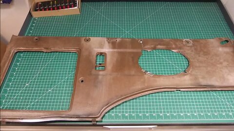
The original factory plastic side panels are showing signs of nearly 40 years of use and abuse. A previous owner of the vehicle had made cutouts for 6" x 9" speakers in the panels. Those openings, especially the screw holes, were badly cracked. I decided to eliminate those speakers as they're in the way of a future battery cage as well as they would be covered by a future fold-down cargo deck. I'll come up with another solution for the rear speakers.
I used the more intact passenger side panel to trace an outline on a half sheet of plywood. I did have to make some minor adjustments to the plywood as it's a flat sheet compared the the molded plastic it was to replace. Both side panels are identical in overall shape. I also didn't cut out any of the openings in the panels at this time. I felt that would weaken the panels with all the fitting work they'll need. That step will be done later in an upcoming video.
One thing that had to go was the carpet over the rear wheel wells. That could be retained, but the curve in the plywood would need to be cut higher to fit the carper underneath. As the carpet was going to interfere with my house battery cage, eliminating the carpet was the best choice. The tar tape that adhered the carpet to the wheel well was scraped off and the residue remove with turpentine. Multiple coats of Herculiner was sprayed onto the bare sheet metal for protection.
Hopefully
Materials used:
1/4" plywood cut to match the factory bed side panels.
1/4" - 20 threaded inserts and screws to replace the factory plastic push pins.
Bed liner spray, needed 1 - 15 oz. can to apply 4 coats to the 2 wheel wells:
https://amzn.to/469MSON
Killer Toy Tops:
https://killertoytops.com/
Some web archive links to soft top companies mentioned.
Kayline Mfg.:
https://web.archive.org/web/19990428193849/http://www.kaylinetops.com/
Specialty Top Co.:
https://web.archive.org/web/20010819040832/http://www.specialtytopco.com/
Can-Back:
https://web.archive.org/web/20010202070000/http://www.can-back.com/
#4Runner #softtop #seatback
11
views
1st Generation Toyota 4Runner, Plywood Seat Backs
1st generation Toyota 4Runner rear seat back replacement.
The original factory rear seats were designed to fold down into a recess below the rear seat bottom cushion and that bottom cushion folded up behind the front seats. With extremely limited access to the rear seats, they are not very useful so I removed them over 20 years ago.
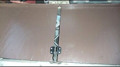
However, the factory seat backs folded down did make a nice extension to the bed. But the cushions used up all the space below. So I built a set of seat backs out of some scrap plywood. I added a raised piece of wood across the front to stop cargo from sliding too far forward. These plywood seat backs open up a nice storage area below. I keep things like spare belts, hoses, and bulky tools under there.
Materials used:
1/4" plywood cut to match the factory rear set backs.
Assorted pieces of wood to make a stiffening frame below the plywood. I mainly used scraps of hardwood left over from an old wooden shop creeper I had.
8 - threaded inserts and screws for the factory hinges
1/8" x 39" x 78" neoprene foam rubber sheet:
https://www.homedepot.com/p/Rubber-Cal-Closed-Cell-Sponge-Rubber-Neoprene-1-8-in-x-39-in-x-78-in-Black-Foam-Rubber-Sheet-02-128-0125/304363423
The foam pad is non-adhesive and simply rolls out under the cargo mat and is held in place that way.
Killer Toy Tops:
https://killertoytops.com/
Some web archive links to soft top companies mentioned.
Kayline Mfg.:
https://web.archive.org/web/19990428193849/http://www.kaylinetops.com/
Specialty Top Co.:
https://web.archive.org/web/20010819040832/http://www.specialtytopco.com/
Can-Back:
https://web.archive.org/web/20010202070000/http://www.can-back.com/
#4Runner #softtop #seatback
3
views
Toyota 4Runner: How To Protect Rear Cargo Mat Plastic Trim
1st generation Toyota 4Runner rear cargo mat plastic trim reinforcement.
Used 1 piece of 1/8" x 1-1/2"W x 48"L aluminum flat bar from Home Depot along with 5 - 10-24 flat head machine screws, 1/4" nylon spacers and thread inserts to beef up the 38 year old plastic trim piece.
Cut in 1/2" from each end approx. 2" towards the center and bend the ends up to match the curve of the trim. Then mark, bend and trim the ends to fit over the trim, file the edges smooth. Mark and drill 5 holes to line up with the screw holes in the bed.
I found the original barbed plastic thread inserts were very loose. I had tried gluing them in place many times over the years, but they always broke loose. So I drilled out the square holes with a letter N drill bit and popped some 10-24 rivnuts in place. Be sure to add some 1/4" tall spacers on top of the inserts to support the plastic trim. Now, the screws through the aluminum can be screwed down tight to make the whole rear trim piece very solid.
Aluminum flat bar:
https://www.homedepot.com/p/Everbilt-1-1-2-in-x-48-in-Aluminum-Flat-Bar-with-1-8-in-Thick-801987/204273937
https://amzn.to/3t1wSj3
Rivet-nuts:
https://amzn.to/3PNQe4b
https://www.mcmaster.com/products/rivnuts/thread-size~10-24/
Spacers for the screws, ~1/4" tall:
https://amzn.to/3Rv7s7C
https://www.mcmaster.com/products/spacers/nylon-unthreaded-spacers/screw-size~no-10/
Killer Toy Tops:
https://killertoytops.com/
Some web archive links to soft top companies mentioned.
Kayline Mfg.:
https://web.archive.org/web/19990428193849/http://www.kaylinetops.com/
Specialty Top Co.:
https://web.archive.org/web/20010819040832/http://www.specialtytopco.com/
Can-Back:
https://web.archive.org/web/20010202070000/http://www.can-back.com/
#4Runner #softtop
2
views
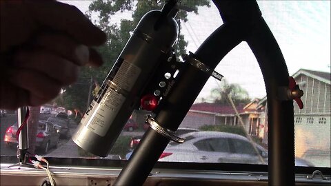
New Fire Extinguisher Mount For The 1st gen 4Runner
Time to replace the ancient fire extinguisher in the back of the 4Runner to get it ready to hit the trails again.
The old extinguisher lacked a good mounting bracket, but it was all I could find at the time. This extinguisher should have been replaced long ago.
Mounting bracket:
https://amzn.to/3LtCx7P
I used some Loctite 638 retaining compound:
https://amzn.to/451locJ
on the threaded end of the release pin. Some feedback on Amazon mentioned this could pull out and mine did. I applied the retaining compound to the threads then clamped the release knob in a vise and screwed the bracket onto that to get it tightened well.
2-1/2 pound fire extinguishers:
https://amzn.to/3RtpZBs
The bracket will hold a larger extinguisher, limited by the band clamps. I went with this size so it would clear my Hi-Lift jack.
Hi-Lift jack mount:
https://www.4crawler.com/4x4/ForSale/HiLiftMount.shtml
Killer Toy Tops:
https://killertoytops.com/
Some web archive links to soft top companies mentioned.
Kayline Mfg.:
https://web.archive.org/web/19990428193849/http://www.kaylinetops.com/
Specialty Top Co.:
https://web.archive.org/web/20010819040832/http://www.specialtytopco.com/
Can-Back:
https://web.archive.org/web/20010202070000/http://www.can-back.com/
#4Runner #softtop
Montebello Ridge Road, 2nd/3rd Visit
Taking another shot at this old road that shows up on the 1895 USGS historical top map. TLDR: 3 strikes and a couple of hits.
This was my 3rd time on this old road, but only the 2nd time I made it up to the bench area.
The last time I came up here, I hadn't yet figured out how to calibrate and build the hill shade maps for off-line use. From my last visit:
"At the top switch back, I should have studied the hill shade map a little more as I now see there are 2 more faint road traces there. If I do get back up here, I think I might try crossing the bench above the old road and see if I can re-join that road where it heads back up the canyon."
I struck out trying to get to the road up the center of the gully, but I did stumble upon a straight segment of road that shows up on the map. I had hoped that road would take me to the excavation that shows up on the map, but dense brush blocked my way from this side just like last time from the main road. I did manage to find the place where the main road that runs up to the top of Montebello Ridge joins in with the road that runs up the next canyon.
There's also hints of a road that heads along the side of the canyon that may join up with a road coming up from gate MB10. I may try coming up from that side at some time.
I think I was wrong last time with this guess:
"This bench is nearly 1000 ft. (300m) below the top of Montebello Ridge, where there are a lot of vineyards, some dating from around the time this road was in use. Not sure if this bench was a used that way or more likely it may have been an orchard of some sort. Hoping that hiking across the bench might run into some old trees or grape vine plants from back then."
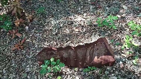
I now think this area may have instead been a cattle grazing area. This was a popular land use on this ridge prior to the establishment of vineyards. I ran across some old barbed wire and what looked like a wooden fence post on the ground along with the rusty stock tank.
If anyone has any information regarding this area, post up in the comment section below. I've been trying to track down a copy of "History of Black Mountain and Monte Bello Ridge", 1959, George Morell.
I'm finally starting to get a feel for how the vegetation mix changes with elevation and what direction it faces here in the canyon. In most cases, below 1700 ft. it's impenetrable brush. This bench runs from 1600 ft. up to about 1700 ft. making exploring up here very difficult. All this brush has grown up since the cattle grazing stopped. It's interesting to see how this area compares to the wide open grassy meadows just up the canyon at Gold Mine Creek. Slightly different soil type along with 1000's of years of indigenous people actively maintaining them and they remain open grass.
About the USGS HTMC:
https://www.usgs.gov/programs/national-geospatial-program/historical-topographic-maps-preserving-past
View/download maps on the TopoView site:
https://ngmdb.usgs.gov/topoview/
More to come...
Subscribe for more content like this
Comment, rate, share & click the bell icon
And as always, thanks for watching
47
views
Waterwheel Creek Trail - Trail, Return Visit
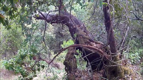
Just like the creek, you won't find this trail on any map either. There's an awesome surprise awaiting at the top!
This trail is brutally steep, many sections above 50% gradient. Up to the grove of trees I stopped at, I traveled 2100 ft. and gained 700 ft. of elevation or 33% average gradient. It looks to be another 0.25 mile and 300 ft. of climbing to get to the official Waterwheel Creek Trail. If you did this same trip down the Canyon trail, Stevens Creek and Montebello Roads, you're looking at ~10 miles. Or you could go up the Canyon Trail, then up the Indian Creek Trail and back down Montebello Road which is ~5 miles or from the official parking lot at the top via the Nature / Canyon / Bella Vista trails and the dirt portion of Montebello road which would be ~9 miles for a loop. So this faint user trail makes an interesting way to efficiently access this area.
Interesting point, after using historic topo maps and the new LIDAR based hill shade maps to find old roads and trails, this one was found using good old fashioned "looking for signs on the ground" technique. However, after losing signs of the trail at a grove of trees, switching over to a hill shade map reveals the presence of an old pond dam and network of roads about 100 yards or meters from there. So this is a "hybrid" hike, combining multiple sources of navigation, along with a 34 mile round trip bike ride to get here.
Round trip of the trail was a bit over a mile (1.65km) and 750 ft. (230m) elevation gain/loss and around 2 hours time.
USGS National Map Viewer w/ Hill Shade:
https://apps.nationalmap.gov/viewer/
More to come...
Subscribe for more content like this
Comment, rate, share & click the bell icon
And as always, thanks for watching
#USGS #HillShade
3
views
AUTO-VOX V5Pro; What it Replaced
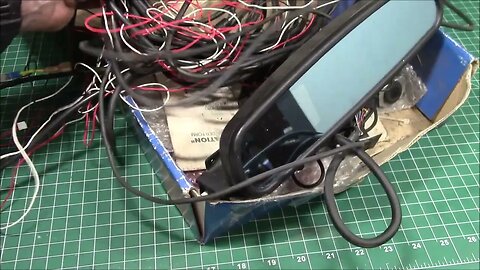
A look at the rear view mirror and my original backup camera in the 1985 Toyota 4Runner.
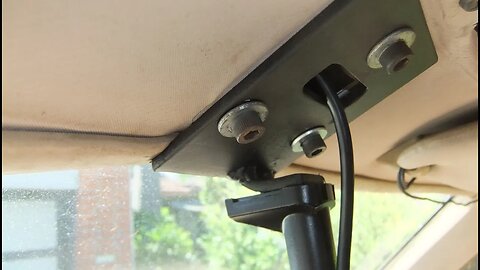
Some 20 years ago, I made a bracket for my old Automan Vision Systems VS-2 rear view mirror camera. This bracket is approx. 3" wide x 4" tall (75mm x 100mm) , with 3 holes drilled to match the OEM mirror bracket. There's a tab welded to the back edge that's drilled and tapped to fit a mirror mounting shoe to. Then there's an opening in the middle to pass the camera cable through. I'm sure there are other ways of doing this, but this is what I came up with 20 years ago and it works.
The old VS-2 system did have some interesting features. The external temperature sensor with on-screen display was nice and something that the V5Pro lacks. It also had the magnetic compass sensor that I could never get to calibrate properly. It only had the alphabetic direction indicators, the V5Pro uses the GPS receiver for the compass display. I like the physical compass display better, although I wish it rotated to keep the direction of travel at the top. The last feature the VS-2 had was a pair of ultrasonic distance detectors that would display an indicator on the display when you got "close to" some object. I could never get these to work reliably. I don't think they had an actual distance measurement displayed, just a symbol when you got within the distance limit.
This is an AUTO-VOX V5Pro Rear View Mirror Camera:
https://amzn.to/3E2efOf
Subscribe for more content like this
Comment, like, share & click the bell icon
And as always, thanks for watching
4
views
1st Generation Toyota 4Runner Rear View Camera
Overview of the rear view mirror camera in the 1985 Toyota 4Runner.
This is an AUTO-VOX V5Pro Rear View Mirror Camera:
https://amzn.to/3E2efOf
I re-used the mirror bracket I made for my old Vision Systems VS-2 rear view mirror camera back around 2000. This bracket is approx. 3" wide x 4" tall (75mm x 100mm) , with 3 holes drilled to match the OEM mirror bracket. There's a tab welded to the back edge that's drilled and tapped to fit a mirror mounting shoe to. Then there's an opening in the middle to pass the camera cable through. I'm sure there are other ways of doing this, but this is what I came up with 20 years ago and it works. One option would be to use a thinner gauge of sheet metal and then bend up a tab from the end and mount the mirror to that. There may also be adapters for the Toyota style mirror mount.
More to come, we'll take a look at the old Vision Systems rear view camera that the V5Pro replaced...
Subscribe for more content like this
Comment, like, share & click the bell icon
And as always, thanks for watching
Gold Mine Creek - Tectonic Block
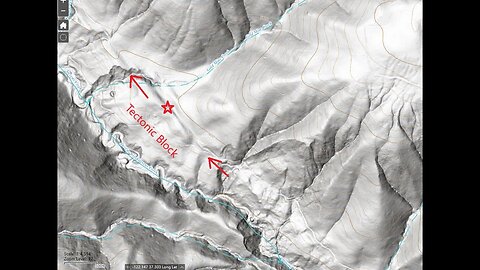
Looking at the tectonic block that sits between the historic and Quaternary traces of the San Andrea fault near Gold Mine Creek.
The hill shade maps really help to show the land forms, especially when combined with the USGS fault maps on Google Earth.
Paper: ENVIRONMENTAL GEOLOGIC ANALYSIS OF THE MONTEBELLO RIDGE MOUNTAIN STUDY AREA:
https://babel.hathitrust.org/cgi/pt?id=mdp.39015042059330&seq=38
"TECTONIC BLOCKS - Large angular to rounded, commonly elliptically shaped masses of relatively hard rocks surrounded by a clay-rich. sheared matrix. Occurs within shear zones and fault gouge. In the shear zones of the Franciscan' rocks, these' blocks range from fist size to masses more than one mile long."
USGS National Map Viewer w/ Hill Shade:
https://apps.nationalmap.gov/viewer/
USGS Quaternary Faults data:
https://earthquake.usgs.gov/education/geologicmaps/qfaults.php
Download the "qfaults.kmz" file from the link on the page, then import that into Google Earth.
Tip: Zoom into your area of interest BEFORE turning on one of the layers. I recall this file has the fault traces, landslide areas and geologic units for a large area and it'll bring your device to a crawl if you enable one of these layers zoomed way out.
You can see how the Canyon Trail, that's mostly built on an old ranch road, follows the historic trace of the San Andreas fault.
If you check out this previous video:
https://youtu.be/_7jxPb-Cvmw?t=366
You can see what this area looked like prior to the road being built.
Montebello Open Space history page:
https://www.openspace.org/preserves/monte-bello#history
More to come...
Subscribe for more content like this
Comment, rate, share & click the bell icon
And as always, thanks for watching
#USGS #HillShade
16
views
The old Gold Mine Creek Road, Part 1
Let's see if I can follow this old road that branches off the Canyon Trail and heads down to lower Gold Mine Creek in the Montebello Open Space Preserve that can be seen on the USGS hill shade map.
Last year, I didn't have my hill shade maps properly calibrated. This is the sort of old road that requires an accurate map as there are long stretches of road that are invisible on the ground.
I've ridden by this part of the Canyon Trail countless times and I've never noticed there's a road here. But once you know where to look, it's there. This is located just down from mile post 2.5. I'm not sure why this road was built. With the large grassy meadows, this area might have been used for cattle grazing and this road was used to access the lower portion of this area. There are other such meadows uphill from the Canyon Trail, although one of them appears to have traces of terracing on the hill shade map. Will need to check that out some time.
This may also be a good way to access Stevens Creek to see what this part of the canyon looks like. From Google Maps and the hill shade map it appears to be quite spectacular but also incredibly hard to access. This section of the canyon was ground zero for the 1838 San Andreas earthquake. That quake likely triggered some slides and earth movement that caused the creek to have to cut a very chaotic canyon here. I suspect it's this very rugged terrain that precluded extending the old Canyon Road up the main branch of Stevens Creek.
USGS National Map Viewer w/ Hill Shade:
https://apps.nationalmap.gov/viewer/
About the USGS HTMC:
https://www.usgs.gov/programs/national-geospatial-program/historical-topographic-maps-preserving-past
View/download maps on the TopoView site:
https://ngmdb.usgs.gov/topoview/
Montebello Open Space history page:
https://www.openspace.org/preserves/monte-bello#history
Some interesting links on native land use practices, which this large meadow may have been an example:
https://www.fs.usda.gov/features/working-with-tribes-oak-groves-meadows
https://oaks.cnr.berkeley.edu/the-ethnobiology-of-californias-oak-woodlands/
https://directives.sc.egov.usda.gov/OpenNonWebContent.aspx?content=25907.wba
https://pubs.usgs.gov/dds/dds-43/VOL_II/VII_C09.PDF
https://scholarworks.calstate.edu/downloads/sn00b2449
More to come...
Subscribe for more content like this
Comment, rate, share & click the bell icon
And as always, thanks for watching
#USGS #HillShade
188
views
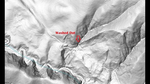
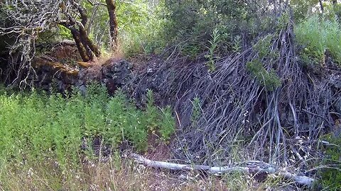
Abandoned Section of the Canyon Road, Return Visit
Finally returned to check out the this puzzling section of the Canyon Trail just below Gold Mine Creek in the Montebello Open Space Preserve.
It appears the small creek that this road crossed here must have had some major flooding and took out a large section of road. Since the ranches in this area seemed to have stopped active operations, whoever built this road probably didn't feel the need to repair it after it washed out.
I've ridden by this part of the Canyon Trail countless times and always wondered why it's different than the rest of the trail. This is located just down from mile post 2.5.
The Canyon Trail shows up down to this location on the 1961 USGS historical topo map, marked as a "Jeep Trail". On that map, it ends right at this point, where it turns into a somewhat modern multi-use trail for about 1/4 mile. Then it turns back into an old single lane dirt road all the way down to where it crosses Stevens Creek at the Lower Table Mountain trail.
When the Open Space District took over in the 1970s, they likely wanted to connect the 2 sections of the Canyon Trail back up to access the lower half of the canyon. So a multi-use trail was built around the washed out section of the old road. This may have been around 1990 or earlier as there was some trail construction below here around that time.
An accurate hill shade map proved to be invaluable in locating the old road, especially at the lower end. Since there's no cell coverage in the canyon, having an off-line version of that map is essential.
USGS National Map Viewer w/ Hill Shade:
https://apps.nationalmap.gov/viewer/
About the USGS HTMC:
https://www.usgs.gov/programs/national-geospatial-program/historical-topographic-maps-preserving-past
View/download maps on the TopoView site:
https://ngmdb.usgs.gov/topoview/
Montebello Open Space history page:
https://www.openspace.org/preserves/monte-bello#history
More to come...
Subscribe for more content like this
Comment, rate, share & click the bell icon
And as always, thanks for watching
#USGS #HillShade
6
views
Adding a Rub Rail to the 4Runner Tailgate
Adding a UHMW Rub Rail to the 1st Generation Toyota 4Runner tail gate to protect the rubber window gasket. This also lets me fill the screw holes left with the Kayline soft top was removed.
Used a 4 foot long piece of black UHMW:
https://www.mcmaster.com/products/uhmw-polyethylene/thickness~3-4/width~3-4/color~black/
Other materials would also work, we use a boat load of UHMW in the business and have a lot of experience working with it.
Killer Toy Tops:
https://killertoytops.com/
Some web archive links to soft top companies mentioned.
Kayline Mfg.:
https://web.archive.org/web/19990428193849/http://www.kaylinetops.com/
Specialty Top Co.:
https://web.archive.org/web/20010819040832/http://www.specialtytopco.com/
Can-Back:
https://web.archive.org/web/20010202070000/http://www.can-back.com/
#4Runner #softtop
4
views
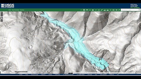
Stevens Creek Landslide Lake Level Visualization
Going by GPS elevation data (1236 ft.), it appears that the landslide lake may have backed up about 1 km above the landslide to where the modern Lower Table Mountain trail starts.
I traced the 1240 foot contour line and filled in that area in a transparent blue color to generate this view of a possible high water point:
https://photos.app.goo.gl/rdm2LovcWbE4EhZw6
Volume estimation:
3000' long x 100' avg.width x 40' avg.depth / 42,000 ft^2/acre = 285 acre-feet or ~351,000 m^3.
This area is where traces of the 1895 road show up. There also seem to be large sediment bars on both sides of the creek where the trail crosses Stevens Creek. The 1895 road seems to have taken advantage of the relatively flat lake deposits between these 2 water crossings. However, the flood and subsequent erosion after the 1906 earthquake and landslide is likely what wiped out a good portion of that old road between the 2 creek crossings.
Stevens Creek flow information:
https://alert.valleywater.org/map?p=sensor&sid=5045&disc=f
This is my hypothesis for what has happened in this section of Stevens Creek to explain the flat nature and deep sediment here. Also ties in the anecdotal evidence from the 1973 geology paper:
ENVIRONMENTAL GEOLOGIC ANALYSIS OF THE MONTEBELLO RIDGE MOUNTAIN STUDY AREA:
https://openlibrary.org/works/OL68916...
Pg. 22 mentions a landslide associated with the 1906 earthquake and this is ground zero for that slide. In fact, the report mentions that slide extended for 1/2 mile, nearly a kilometer, along the canyon.
USGS National Map Viewer w/ Hill Shade layers:
https://apps.nationalmap.gov/viewer/
More to come...
Subscribe for more content like this
Comment, rate, share & click the bell icon
And as always, thanks for watching
#USGS #HillShade #geology #earthquake #tectonicplates
3
views
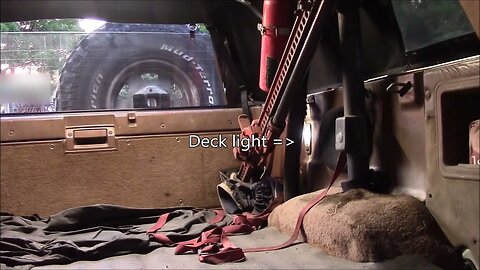
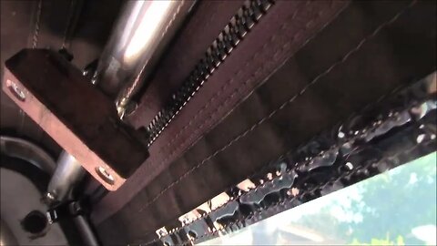
Adding Overhead Lighting to the Soft Top, Part 3
After years of not using the factory deck light switch, I found it no longer worked reliably when I connected in the new overhead light. Some contact cleaner sprayed into the switch and operating the switch many times was able to restore normal operation.
This new overhead light is tied into the factory deck (or room) light and can be operated from the dash or from the back of the bed. Having the overhead light on the rear hoop of the soft top gets it up above the factory roll bar, so it's no longer in the way like the old trouble light was.
Many years ago I had modified the factory deck light to improve it's usefulness. Originally, it had an 3W incandescent festoon bulb and required the vehicle running lights to be on. You could then turn that lamp on with it's built-in switch or from the dash switch, wired up as a 3-way light circuit. I initially re-powered that switch to work off constant 12V power:
https://www.4crawler.com/4x4/CheapTricks/index.shtml#DeckLightMod
I had also installed a 6-LED festoon bulb that put out much more light and used 1/5 the current of the original 3W incandescent bulb.
Later I changed that light to work off of accessory power but I think I'll return to constant power. I also tapped into the bulb wiring and ran that to a 12V power socket that I could plug the 12V LED trouble light into. Over time, that early design trouble light started to break down so I didn't use it a lot. When I pulled to Kayline top off, I removed that old light and looked for a new solution.
I found this linear "rail lights":
18.5" Pivoting LED Rail Light - Integrated Rocker Switch
https://www.superbrightleds.com/
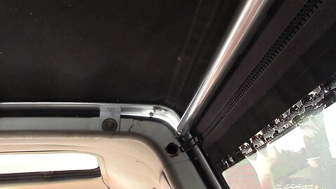
I wanted something that could be attached to the support tubes of the soft top without drilling, be adjustable in angle and have a built-in switch. One will be placed across the back of the bed and connected to the old deck light wiring. The other two will be up front on either side of the bed. My 12V fridge will be placed on the driver's side so one light will be over that. The other one will be over the area behind the passenger seat where I have gear stored below.
I found some 3/4" conduit clamps were the right size and shape to clamp to the support tubes. I added some heat shrink tubing to the center of the clamps to grip the tubes tighter and to help protect the canvas top where it made contact with the clamps.
In the next video, we'll take a look at why the old trouble light failed...
Killer Toy Tops:
https://killertoytops.com/
More to come...
Subscribe for more content like this
Comment, like, share & click the bell icon
And as always, thanks for watching
#4Runner #softtop
6
views
Adding Overhead Lighting to the Soft Top, Part 2
Working on the clamps that will be used to attach the LED rail lights to the support tubes inside the soft top. I didn't want to drill any holes in the thin aluminum tubes. I used some hardwood blocks cut from an old shipping pallet to screw the light end caps into and also to attach the conduit clamps to. It took a lot of back and forth trips from the shop to the soft top to work out how to fit these clamps in place without creating a wear point for the canvas.
Many years ago I had modified the factory deck light to improve it's usefulness. Originally, it had an incandescent festoon bulb and required the vehicle running lights to be on. You could then turn that lamp on with it's built-in switch or from the dash switch, wired up as a 3-way light circuit. I initially re-powered that switch to work off constant 12V power:
https://www.4crawler.com/4x4/CheapTricks/index.shtml#DeckLightMod
Later I changed that to accessory power but I think I'll return to constant power. I also tapped into the bulb wiring and ran that to a 12V power socket that I could plug the 12V LED trouble light into. Over time, that early design trouble light started to break down so I didn't use it a lot. When I pulled to Kayline top off, I removed that old light and looked for a new solution.
I found this linear "rail lights":
18.5" Pivoting LED Rail Light - Integrated Rocker Switch
https://www.superbrightleds.com/
I wanted something that could be attached to the support tubes of the soft top without drilling, be adjustable in angle and have a built-in switch. One will be placed across the back of the bed and connected to the old deck light wiring. The other two will be up front on either side of the bed. My 12V fridge will be placed on the driver's side so one light will be over that. The other one will be over the area behind the passenger seat where I have gear stored below.
I found some 3/4" conduit clamps were the right size and shape to clamp to the support tubes. I added some heat shrink tubing to the center of the clamps to grip the tubes tighter and to help protect the canvas top where it made contact with the clamps.
In the next video, we'll get the lights installed and at least one wired up...
Killer Toy Tops:
https://killertoytops.com/
More to come...
Subscribe for more content like this
Comment, like, share & click the bell icon
And as always, thanks for watching
8
views
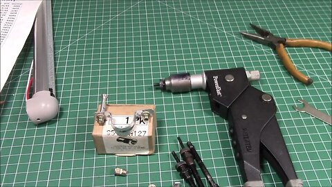
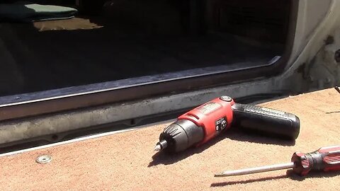
Repaired Rivet Nut Installer
In order to install the conduit clamps that will attach the rail lights to the soft top support tubes, I needed to use my old Rivet Nut installer, but it broke. This is how I repaired it.
This is a PowerFast 37005 Rivet Nut installation tool. It came as a kit with hardware to install 6-32, 8-32, 10-24 and 1/4-20 rivet nuts.
I've had this tool for many years. Over time, the aluminum nose piece of the tool started to collapse and then crack and it finally let go with a bang when I tried to use it this time. I don't think this tool is available any longer and I could find no spare parts.
Here's a listing for a used tool:
https://www.tzsupplies.com/nice-power-fast-no-37005-i6162091/
It looks like that one has a solid nose piece on it, interesting.
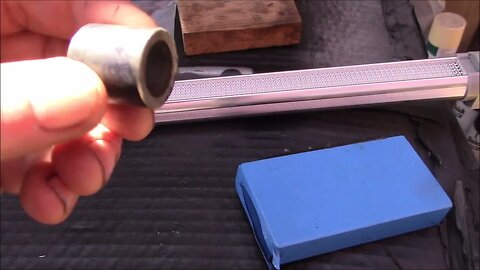
I ended up fashioning a 1" diameter steel rod that fits over the broken end of the original nose piece. This has the M10x1.0 thread for the supplied mandrels to screw into. As the nose piece was just over 3/4" diameter, I drilled the end of the steel to 3/4" then turned down the nose piece to slide inside. The part was made a bit over sized and was then trimmed down to fit, as I had no "before" measurements to go by.
All in all, this repaired tool works better than it did when new. Without the flexing of the soft metal in the nose piece, it's a lot easier to get a good crimp with the rivet nuts.
More to come, installing rivet nuts the rest of the conduit clamps...
Subscribe for more content like this
Comment, like, share & click the bell icon
And as always, thanks for watching
Intro/Outro:
Louisiana Fairytale by Austin Rogers
https://web.archive.org/web/20170402222425/http://drfiddle.com/show_tune.php?id=94
5
views
Adding Overhead Lighting to the Soft Top, Part 1
Replacing the old LED trouble light I used to have in the back of the 4Runner with some modern LED fixtures.
The original 12V trouble light was purchased around 2000 from Grizzly.com. It came with a hard wired 12V power supply. I figured I could replace that with a lighter plug and use it in the truck. While that did work for a while, it became apparent that the power supply must have had current regulation to keep from over driving the LEDs. As a result, many of the LEDs burned out.
Many years ago I had modified the factory deck light to improve it's usefulness. Originally, it had an incandescent festoon bulb and required the vehicle running lights to be on. You could then turn that lamp on with it's built-in switch or from the dash switch, wired up as a 3-way light circuit. I initially re-powered that switch to work off constant 12V power:
https://www.4crawler.com/4x4/CheapTricks/index.shtml#DeckLightMod
Later I changed that to accessory power but I think I'll return to constant power. I also tapped into the bulb wiring and ran that to a 12V power socket that I could plug the 12V LED trouble light into. Over time, that early design trouble light started to break down so I didn't use it a lot. When I pulled to Kayline top off, I removed that old light and looked for a new solution.
I found this linear "rail lights":
18.5" Pivoting LED Rail Light - Integrated Rocker Switch
https://www.superbrightleds.com/
I wanted something that could be attached to the support tubes of the soft top, be adjustable in angle and have a built-in switch. One will be placed across the back of the bed and connected to the old deck light wiring. The other two will be up front on either side of the bed. My 12V fridge will be placed on the driver's side so one light will be over that. The other one will be over the area behind the passenger seat where I have gear stored below.
I found some 3/4" conduit clamps were just the right size and shape to clamp to the support tubes. I added some heat shrink tubing to the center of the clamps to grip the tubes tighter and to help protect the canvas top if it made contact with the clamps.
In the next video, I'll show you the final clamp design which turned out to be more complicated that originally thought...
Killer Toy Tops:
https://killertoytops.com/
Some web archive links to soft top companies mentioned.
Kayline Mfg.:
https://web.archive.org/web/19990428193849/http://www.kaylinetops.com/
Specialty Top Co.:
https://web.archive.org/web/20010819040832/http://www.specialtytopco.com/
Can-Back:
https://web.archive.org/web/20010202070000/http://www.can-back.com/
9
views
Killer Toy Tops: Toyota 4Runner Soft Top Install, Part 2
Killer Toy Tops: 1st Generation Toyota 4Runner Soft Top Installation.
Fixing one installation mistake by re-installing the factory cab gasket that was removed many years ago for the Kayline soft top installation. Luckily, I still had that part and it was installed with some Gorilla Clear Grip Contact Adhesive:
https://amzn.to/44AFI4N
This was also a good time to get the old Vision Systems VS-2 backup camera wiring removed and the new AutoVox V5pro backup camera wire run through the headliner to the mirror location:
https://amzn.to/3NGPZ8J
The old backup camera, a Vision System VS-2, had a huge mess of cables, since there was the power/video cable for the camera, the power and ground cable, an external temperature sensor along with a pair of ultra sonic distance sensors for backing up (I never got these to work reliably). This camera was better than nothing, with the hard to see out of clear vinyl window. But it had a tiny display on the mirror, maybe 1.5" diagonal. And the camera itself was useless if there was any bright light in view, like sun or headlights, as it was completely over exposed. The AutoVox V5pro backup camera has a single 8-conductor cable that fit through the new wire loom easily.
I also ran an 8-conductor Cat5 cable up for my future Raspberry Pi based OpenAuto Pro head unit. I'll be able to run signals for auto dimming when the headlights are on, accessory power, etc. up to the display:
https://bluewavestudio.io/
Killer Toy Tops:
https://killertoytops.com/
Some web archive links to soft top companies mentioned.
Kayline Mfg.:
https://web.archive.org/web/19990428193849/http://www.kaylinetops.com/
Specialty Top Co.:
https://web.archive.org/web/20010819040832/http://www.specialtytopco.com/
Can-Back:
https://web.archive.org/web/20010202070000/http://www.can-back.com/
5
views
Killer Toy Tops: Toyota 4Runner Soft Top Install, Part 1
Killer Toy Tops: 1st Generation Toyota 4Runner Soft Top Installation.
After 20+ years of use, time to replace the old Kayline SoftTop. With the issues I ran into with vinyl shrinking over time, I wanted to go with a Sunbrella type fabric instead. This should hold up over time and not get stiff in colder weather. Also, I never liked the zip up clear vinyl window in the back. So I opted for the Killer Toy Tops design which will allow use of the rear glass window.
Killer Toy Tops:
https://killertoytops.com/
Check out the web page below for more information:
https://www.4crawler.com/4x4/CheapTricks/SoftTop/index.shtml#SoftTopInstallKit
Some web archive links to soft top companies mentioned.
Kayline Mfg.:
https://web.archive.org/web/19990428193849/http://www.kaylinetops.com/
Specialty Top Co.:
https://web.archive.org/web/20010819040832/http://www.specialtytopco.com/
Can-Back:
https://web.archive.org/web/20010202070000/http://www.can-back.com/
6
views
Kayline / STC: 1st gen 4Runner Soft Top Install Kit
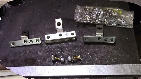
Here's our easy install Kayline/STC soft top install kit for the 1st generation Toyota 4Runner models (1984-1989).
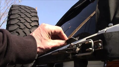
As designed, this soft top required drilling many holes for sheet metal screws to attach the soft top frame to the bed rails and back of the cab. In rust prone environments, this could cause issues and it also made removal and re-installation time consuming.
My buddy Tom, who originally owned this soft top, and I came up with the idea of riveting tee brackets to the frame to make use of the factory bolt holes. This greatly reduced the number of holes that needed to be drilled into the body sheet metal and made installation and removal much easier. I recall Tom made and installed these brackets on this top frame. They are still working fine some 25 years later.
Check out the web page below for more information:
https://www.4crawler.com/4x4/CheapTricks/SoftTop/index.shtml#SoftTopInstallKit
Some web archive links to soft top companies mentioned.
Kayline Mfg.:
https://web.archive.org/web/19990428193849/http://www.kaylinetops.com/
Specialty Top Co.:
https://web.archive.org/web/20010819040832/http://www.specialtytopco.com/
Can-Back:
https://web.archive.org/web/20010202070000/http://www.can-back.com/
You can also make your own install kit with 3" tee repair brackets, 1"x1/8" flat bar and some pop rivets, available from most hardware stores.
This never started out to be a product. I had published a web page with information on how I installed this soft top on my 4Runner. Then started getting contacted by folks wanting to know if we could make them a set of brackets for their soft top and a product was born. We still make a few of these every year. Someone always seems to run across an old soft top and is looking for an easier way to install it.
5
views
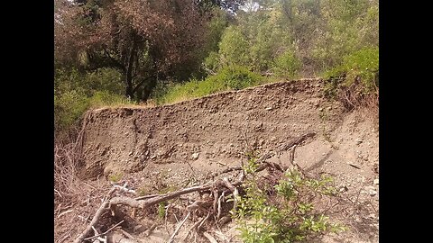
Stevens Creek Landslide Lake Deposit Layers
Taking a closer look at the sediment layers along Stevens Creek now that the water levels have dropped.
This layering is likely quite complex. After a landslide dams up the creek down stream, water will slowly back up behind that dam. Eventually water will over top the landslide debris and start eroding down, causing the lake to drain. Then, you have the erratic nature of high flows in the creek that are capable of moving large amounts of sediment. As a result, you may have a sediment layer deposited while the water level is rising or when it's falling. The sediment will be deposited at the point the flowing water hits the standing water. Thus, the point of deposition may move up and down the canyon over a single landslide dam event. Add to that, multiple landslides over the milennia, with the creek cutting a new channel in between slides and this is what you get. The key point is that this sediment was likely not deposited in a single event.
You can see how intermittent the flow is in Stevens Creek. In the '21-'22 winter, there were no instances where the flow exceeded 240 CFS, as measured near the inlet to Stevens Creek Reservoir, ~5 miles downstream from here. In the '22-'23 winter, there were 4 times the flow got over 600 CFS., and this was a record rainfall year. On average, there may only be 1 or 2 instances (typically only a few days in duration) per year where there's sufficient flow to transport large amounts of sediment downstream and create one of these layers.
Stevens Creek flow information:
https://alert.valleywater.org/map?p=sensor&sid=5045&disc=f
This is my hypothesis for what has happened in this section of Stevens Creek to explain the flat nature and deep sediment here. Also ties in the anecdotal evidence from the 1973 geology paper.
Paper: ENVIRONMENTAL GEOLOGIC ANALYSIS OF THE MONTEBELLO RIDGE MOUNTAIN STUDY AREA:
https://openlibrary.org/works/OL68916...
Pg. 22 mentions a landslide associated with the 1906 earthquake and this is ground zero for that slide. In fact, the report mentions that slide extended for 1/2 mile, nearly a kilometer, along the canyon.
USGS National Map Viewer w/ Hill Shade layers:
https://apps.nationalmap.gov/viewer/
More to come...
Subscribe for more content like this
Comment, rate, share & click the bell icon
And as always, thanks for watching
#USGS #HillShade #geology #earthquake #tectonicplates
11
views