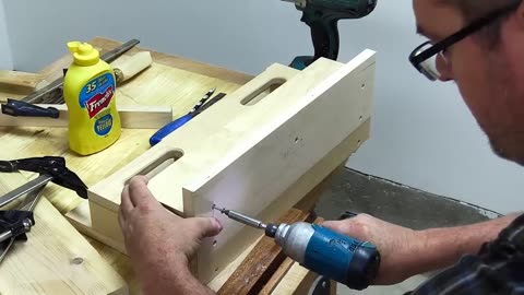
Making The Coolest Small Parts Organizer - Woodworking
Creating a small parts organizer can be both a practical and enjoyable woodworking project. A well-designed organizer helps keep your workspace tidy and ensures that small items like screws, nails, bolts, and other hardware are easy to find. Here’s a step-by-step guide to making a cool small parts organizer:
Materials and Tools Needed
Materials:
Plywood or hardwood (1/2" thick for the main structure)
Plywood or MDF (1/4" thick for drawers)
Small drawer knobs or handles
Wood glue
Wood screws or brad nails
Drawer slides (optional)
Paint, stain, or finish (optional)
Tools:
Table saw or circular saw
Miter saw or hand saw
Drill and drill bits
Clamps
Measuring tape or ruler
Square
Sandpaper or sander
Wood glue applicator
Brad nailer (optional)
Paintbrush (if finishing)
Steps to Make a Cool Small Parts Organizer
1. Design and Plan
Decide on the dimensions and number of drawers or compartments you want in your organizer. For this example, let's create an organizer with a main box and several small drawers.
2. Cut the Main Box Pieces
Back Panel: Cut a piece of plywood to the desired height and width of the organizer (e.g., 24" x 18").
Top and Bottom Panels: Cut two pieces for the top and bottom (e.g., 24" x 6").
Side Panels: Cut two side panels to match the height of the back panel and the depth of the top and bottom panels (e.g., 18" x 6").
3. Assemble the Main Box
Join Panels:
Apply wood glue to the edges of the top and bottom panels.
Attach them to the side panels using wood screws or brad nails. Ensure everything is square.
Attach the back panel to the assembled frame using wood glue and screws or nails.
4. Create Drawer Compartments
Internal Dividers: Cut internal divider pieces to create compartments within the main box. The size and number of dividers depend on your design (e.g., 1/4" thick pieces cut to fit horizontally and vertically within the box).
Install Dividers:
Measure and mark the positions for the dividers inside the main box.
Attach the dividers using wood glue and clamps. Ensure they are evenly spaced and perpendicular to the panels.
5. Make the Drawers
Drawer Fronts: Cut pieces for the drawer fronts (e.g., 1/2" thick plywood, cut to fit the width and height of the drawer openings).
Drawer Sides: Cut pieces for the drawer sides and back (e.g., 1/4" thick plywood, cut to fit the depth of the drawers).
Drawer Bottoms: Cut pieces of 1/4" plywood or MDF to fit the bottom of the drawers.
Assemble Drawers:
Apply wood glue to the edges of the side pieces and attach them to the drawer fronts and back pieces using brad nails or screws.
Attach the bottom piece to the drawer using wood glue and brad nails or screws.
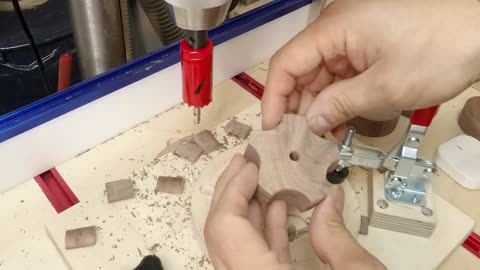
6. Install Drawer Knobs or Handles
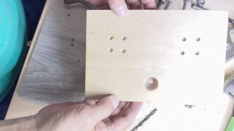
Drill Holes: Drill holes in the center of each drawer front for the knobs or handles.
Attach Knobs/Handles: Attach the knobs or handles using screws provided with them.
7. Optional: Install Drawer Slides
Attach Slides: If using drawer slides, attach them to the sides of the drawers and the inside of the organizer’s compartments according to the manufacturer's instructions.
8. Sand and Finish
Sand: Sand all surfaces of the organizer and drawers to smooth any rough edges.
Finish: Apply paint, stain, or finish of your choice to the organizer. Allow it to dry completely before use.
Final Assembly and Usage
Insert Drawers: Once everything is dry, insert the drawers into the compartments.
Label Drawers: For added organization, consider labeling the drawers to indicate their contents.
By following these steps, you'll create a cool and functional small parts organizer that keeps your workspace tidy and your small items easily accessible. This project not only enhances your organization but also adds a custom piece of furniture to your workshop.
5
views
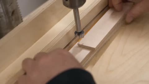
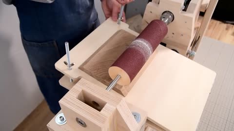
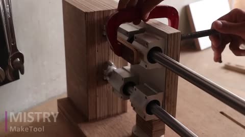
2-way Drill Press Machine Handmade Drill stand
Creating a 2-way drill press machine involves building a handmade drill stand that allows for both vertical and horizontal drilling. This guide will walk you through the process of making a versatile and sturdy drill stand.
Materials and Tools Needed
Materials:
Hardwood or plywood for the base and supports
Metal rods or pipes for the guide rails
Bearings or bushings for smooth movement
Screws, nuts, and bolts
Springs for the return mechanism
Clamps for securing the drill
Wood glue
Rubber feet for stability
Hinges for the tilting mechanism
T-tracks for adjustability
Knobs for easy adjustments
Tools:
Drill and drill bits
Saw (circular saw, table saw, or hand saw)
Measuring tape or ruler
Square
Screwdriver
Wrench
Sandpaper or sander
Clamps
Chisel (optional, for fine adjustments)
Steps to Make a 2-way Drill Press Machine
1. Cut the Base and Support Pieces
Base: Cut a piece of hardwood or plywood to serve as the base, typically around 18” x 18” for stability.
Vertical Supports: Cut two pieces of hardwood or plywood for the vertical supports, approximately 18” high.
Horizontal Arm: Cut another piece for the horizontal arm, about 12” to 15” long, depending on the reach you need.
2. Assemble the Base and Vertical Supports
Attach Supports to Base:
Secure the vertical supports to the base using screws and glue, ensuring they are perpendicular to the base and parallel to each other. Use a square to check alignment.
Install Guide Rails:
Drill holes in the vertical supports to fit the guide rails. Insert metal rods or pipes through these holes and secure them with screws or epoxy.
3. Create the Drill Carriage
Carriage Platform:
Cut a piece of hardwood or plywood to serve as the carriage platform. This platform will hold the drill and move along the guide rails.
Bearing or Bushing Housing:
Attach bearings or bushings to the carriage platform. These will slide along the guide rails, ensuring smooth and accurate movement.
Drill Holder:
Attach an adjustable clamp or custom-made holder to the carriage platform to secure the drill. Ensure it can be easily adjusted and removed.
4. Install the Return Mechanism
Springs:
Attach springs to the top of the vertical supports and the carriage platform. These springs will help return the drill to the upright position after drilling.
5. Add Horizontal Drilling Capability
Hinged Horizontal Arm:
Attach a hinge to one of the vertical supports near the top, connecting it to the horizontal arm. This hinge will allow the horizontal arm to pivot.
Horizontal Guide Rails:
Install guide rails on the horizontal arm similar to those on the vertical supports. Ensure the carriage platform can move along these rails for horizontal drilling.
Locking Mechanism:
Add a locking mechanism to secure the horizontal arm in place when not in use, and to adjust the angle when needed.
6. Add Adjustable Stops and Depth Control
Vertical Stop:
Install a T-track or strip of wood with pre-drilled holes along the vertical support. Create a stop block that can be secured to this track using a bolt and knob.
Horizontal Stop:
Attach another T-track along the horizontal arm. Create a stop block that fits into this track and can be adjusted to control the drilling position.
7. Install Measurement Scales and Angle Guides
Ruler Scale:
Attach a ruler or measuring tape along the vertical support for easy reference when adjusting the drilling depth. Add another scale along the horizontal arm.
Angle Guide:
Install a protractor scale at the hinge to measure the angle of the horizontal arm. Ensure it is easy to read and adjust.
8. Enhance Stability and Precision
Rubber Feet:
Attach rubber feet to the bottom of the base to prevent slipping and provide stability.
Guide Rail Stiffeners:
Add additional support to the guide rails by attaching stiffeners or additional rails parallel to the existing ones.
Testing and Final Adjustments
Test Movement:
Slide the drill carriage up and down the vertical and horizontal guide rails to ensure smooth movement.
Check Alignment:
Ensure the drill bit is perfectly perpendicular to the base and parallel when horizontal. Adjust the vertical supports or carriage if necessary.
Secure Drill:
Place your drill in the holder and secure it firmly. Test the return mechanism by lowering and releasing the drill.
Usage Tips
Vertical Drilling:
Use the vertical guide rails for standard drilling tasks. Adjust the vertical stop to set the desired drilling depth.
Horizontal Drilling:
Pivot the horizontal arm into position for horizontal drilling. Use the horizontal stop to set the drilling distance from the vertical supports.
Angle Drilling:
Adjust the angle of the horizontal arm using the protractor scale and locking mechanism for precise angle drilling.
By following these steps, you will create a versatile and functional 2-way drill press machine that allows for both vertical and horizontal drilling. This handmade drill stand will significantly enhance the accuracy and efficiency of your drilling tasks.
5
views
Making a 6 in 1 Drill Press( Drill Guide ) Part 3
In Part 3, we will add more advanced features to our 6-in-1 drill press (drill guide) to further enhance its versatility and usability. This part will cover the addition of a dust collection system, an integrated lighting system, and provisions for different types of drills and attachments.
Steps to Make a 6-in-1 Drill Press (Drill Guide) - Part 3
15. Add a Dust Collection System
A dust collection system helps keep your work area clean and improves visibility during drilling.
Dust Collection Port:
Attach a dust collection port near the base of the vertical supports. This can be a simple PVC pipe or a commercially available dust port adapter.
Ensure the port is positioned to capture dust directly from the drilling area.
Hose Attachment:
Connect a flexible hose from the dust port to a shop vac or dust collection system. Secure the hose with clamps or zip ties to prevent it from coming loose.
Hood or Shroud:
Create a hood or shroud around the drill bit area using clear plastic or plexiglass. This helps direct dust towards the collection port while allowing visibility.
16. Install an Integrated Lighting System
Proper lighting ensures better visibility and accuracy when drilling.
LED Strip or Lamp:
Attach an LED strip or small adjustable lamp to the vertical supports or the carriage platform. LED lights are preferred due to their low heat output and bright, focused light.
Power Supply:
Connect the lighting system to a power source. If using an LED strip, you may need a power adapter that converts AC to the appropriate DC voltage.
Switch:
Install a switch on the vertical support to easily turn the lights on and off.
17. Add Provisions for Different Types of Drills and Attachments
Enhancing the drill guide to accommodate various drills and attachments increases its versatility.
Universal Drill Mount:
Design a universal mount or clamp system that can accommodate different types and sizes of drills. This can be done using adjustable clamps or a quick-release mechanism.
Router Attachment:
Modify the carriage platform to hold a compact router for precision milling tasks. Ensure the router is securely mounted and can be easily swapped with the drill.
Dremel Tool Holder:
Create a holder for a Dremel tool or rotary tool. This can be a simple bracket that attaches to the carriage platform, allowing for detailed work and small-scale drilling.
18. Add Measurement Scales and Guides
Measurement scales and guides improve accuracy and repeatability.
Ruler Scale:
Attach a ruler or measuring tape along the vertical support for easy reference when adjusting the drilling depth.
Add another scale along the horizontal base to measure the distance from the drill bit to the edge of the workpiece.
Angle Guides:
Install a protractor scale at the base for precise angle drilling. Ensure it is easy to read and adjust.
19. Final Enhancements and Adjustments
Smooth Movement:
Ensure all moving parts, including the carriage platform and guide rails, move smoothly without resistance. Lubricate if necessary.
Secure Fastenings:
Double-check all screws, bolts, and nuts to ensure everything is securely fastened. Tighten any loose components.
Safety Features:
Add safety features such as a protective shield around the drill bit area to prevent accidental contact.
Ensure all electrical components, including the lighting and dust collection systems, are properly insulated and safe to use.
Testing and Usage
Comprehensive Test:
Test the drill press with different types of drills and attachments to ensure compatibility and functionality.
Check the dust collection system by drilling into various materials and observing dust capture efficiency.
User Instructions:
Create a set of user instructions for adjusting the various features, including the angle guide, depth control, and drill mount adjustments.
Safety Check:
Conduct a final safety check to ensure all features are operating correctly and safely.
By following these steps, you will complete the transformation of your basic drill guide into a comprehensive 6-in-1 drill press capable of handling a wide range of drilling, milling, and detailed work tasks. This enhanced tool will be a valuable addition to your workshop, offering versatility, precision, and efficiency.
8
views
Making a 6 in 1 Drill Press( Drill Guide ) Part 2
Continuing from Part 1, we will now focus on adding features to our basic drill press/drill guide to enhance its functionality and make it a versatile 6-in-1 tool. This part will cover adjustable stops, depth control, angle drilling capabilities, and additional enhancements for precision and ease of use.
Steps to Make a 6-in-1 Drill Press (Drill Guide) - Part 2
10. Add Adjustable Stops
Adjustable stops allow you to set the exact position where the drill will stop, ensuring consistent hole depths and repeatability.
Horizontal Stop:
Attach a T-track or a strip of wood with pre-drilled holes along the front edge of the base.
Create a stop block that can be secured to the T-track or strip using a bolt and knob. This block will slide along the track and can be locked in place at the desired position.
Vertical Stop:
Attach another T-track vertically along one of the vertical supports.
Create a stop block that fits into this T-track and can be secured with a bolt and knob. This block will limit the upward movement of the carriage, controlling the maximum depth of the drill.
11. Install Depth Control Mechanism
Depth control ensures that you can drill holes to precise depths without guesswork.
Depth Rod:
Attach a depth rod to the carriage platform. This rod should move with the platform as it slides up and down.
Drill a hole through one of the vertical supports where the rod can pass through.
Depth Stop:
Add a stop collar or an adjustable block on the depth rod. This stop can be adjusted and locked in place to set the desired drilling depth.
12. Add Angle Drilling Capability
Allowing the drill guide to tilt for angled drilling adds significant versatility.
Tilting Mechanism:
Create a hinge system at the base of the vertical supports. This can be done by attaching the vertical supports to the base with heavy-duty door hinges or specialized pivot hinges.
Ensure the hinges are strong enough to support the weight of the drill and the carriage.
Angle Adjustment:
Attach an adjustable angle bracket or protractor gauge to one side of the vertical supports. This gauge should have a scale for measuring angles.
Add a locking mechanism, such as a bolt and knob, to secure the vertical supports at the desired angle.
13. Enhance Precision and Stability
Improving precision and stability ensures better performance and safety.
Guide Rail Stiffeners:
Add additional support to the guide rails by attaching stiffeners or additional rails parallel to the existing ones. This reduces flex and ensures smooth, accurate movement.
Carriage Lock:
Install a locking mechanism on the carriage platform to hold it in place when needed. This can be a simple bolt that tightens against the guide rails.
Anti-Slip Base:
Attach a rubber or non-slip mat to the bottom of the base to prevent movement during operation.
14. Install a Laser Guide (Optional)
A laser guide helps in aligning the drill bit precisely on the workpiece.
Laser Module:
Purchase a laser guide module designed for drill presses. These modules are typically available at hardware stores or online.
Mounting:
Attach the laser module to the vertical supports or the carriage platform. Ensure it is aligned with the drill bit.
Power Source:
Connect the laser module to a power source as per the manufacturer's instructions.
Testing and Final Adjustments
Test All Features:
Test each feature, including the adjustable stops, depth control, and angle drilling capabilities. Ensure they work smoothly and accurately.
Fine-Tuning:
Make any necessary adjustments to the alignment, tension, and locking mechanisms to ensure precision and ease of use.
Safety Check:
Ensure all moving parts are secure and that there are no loose components. Check the stability of the base and the carriage movement.
By following these steps, you will have transformed a basic drill press/drill guide into a versatile 6-in-1 tool capable of handling a variety of drilling tasks with precision and ease. This enhanced drill press will be a valuable addition to your workshop, providing increased functionality and efficiency for your projects.
6
views
Making a 6 in 1 Drill Press( Drill Guide ) Part 1
Creating a versatile 6-in-1 drill press/drill guide is a useful project that can greatly enhance the accuracy and efficiency of your drilling tasks. This guide will walk you through the first part of the process, focusing on the design and assembly of the base and the primary vertical support mechanism.
Materials and Tools Needed
Materials:
Hardwood or plywood for the base and support structure
Metal rods or pipes for the guide rails
Bearings or bushings (for smooth movement of the drill carriage)
Screws, nuts, and bolts
Springs (for return mechanism)
Clamps (for securing the drill)
Wood glue
Rubber feet (for stability)
Tools:
Drill and drill bits
Saw (circular saw, table saw, or hand saw)
Measuring tape or ruler
Square
Screwdriver
Wrench
Sandpaper or sander
Clamps
Chisel (optional, for fine adjustments)
Steps to Make a 6-in-1 Drill Press (Drill Guide) - Part 1
1. Design and Plan
Before starting the build, create a detailed plan or sketch of your drill press. Determine the dimensions based on the size of your drill and the desired height and reach of the press.
2. Cut the Base
Base: Cut a piece of hardwood or plywood to serve as the base. A typical size might be 12” x 12” or larger, depending on your needs. Ensure it is thick and sturdy enough to provide stability.
3. Prepare the Vertical Supports
Vertical Supports: Cut two pieces of hardwood or plywood for the vertical supports. These will hold the guide rails and allow the drill carriage to move up and down. The height should be at least 12” to 18” depending on the size of your drill and the maximum height you need for your projects.
4. Attach the Vertical Supports to the Base
Secure the vertical supports to the base using screws and glue. Ensure they are perfectly perpendicular to the base and parallel to each other. Use a square to check for accuracy.
5. Install the Guide Rails
Guide Rails: Use metal rods or pipes as guide rails. Cut them to the appropriate length, matching the height of your vertical supports.
Drill holes in the vertical supports to fit the guide rails. The holes should be aligned to ensure smooth movement of the drill carriage.
Insert the guide rails into the holes and secure them in place with screws or epoxy.
6. Create the Drill Carriage
Carriage Platform: Cut a piece of hardwood or plywood to serve as the carriage platform. This platform will hold the drill and slide up and down the guide rails.
Bearing or Bushing Housing: Attach bearings or bushings to the carriage platform. These will slide along the guide rails, ensuring smooth and accurate movement.
Position the bearings or bushings on the carriage platform so they align with the guide rails. Attach them securely with screws or bolts.
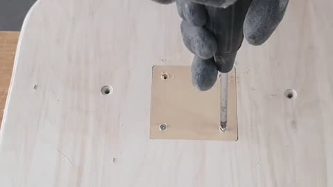
7. Attach the Drill Holder
Drill Holder: Create a holder or clamp to secure the drill to the carriage platform. This can be done using adjustable clamps, a custom-made wooden bracket, or metal brackets.
Attach the drill holder to the carriage platform, ensuring it holds the drill firmly and allows for easy adjustment and removal.
8. Install the Return Mechanism
Springs: Attach springs to the top of the vertical supports and the carriage platform. These springs will help return the drill to the upright position after drilling.
Ensure the springs are strong enough to lift the weight of the drill but not too stiff to hinder smooth movement.
9. Add Stability Features
Rubber Feet: Attach rubber feet to the bottom of the base to prevent slipping and provide stability.
Bracing: If needed, add diagonal braces between the vertical supports and the base for added stability.
Testing and Adjustments
Test Movement: Slide the drill carriage up and down to ensure smooth movement along the guide rails. Make any necessary adjustments to the bearings or bushings.
Check Alignment: Ensure the drill bit is perfectly perpendicular to the base. Adjust the vertical supports or carriage if necessary.
Secure Drill: Place your drill in the holder and secure it firmly. Test the return mechanism by lowering and releasing the drill.
This completes the first part of the project. In the next part, you can focus on adding more features to make it a true 6-in-1 tool, such as adjustable stops, depth control, angle drilling capabilities, and more.
5
views
How To Make A Wooden Bar Clamp
Making a wooden bar clamp is a straightforward project that can be accomplished with basic woodworking tools and materials. Here's a step-by-step guide:
Materials and Tools Needed
Materials:
Hardwood for the bars and jaws (e.g., oak, maple, or walnut)
Threaded rod (e.g., 3/8" or 1/2" diameter)
Nuts and washers to fit the threaded rod
Wood glue
Wood screws
Epoxy (optional, for added strength)
Tools:
Saw (circular saw, miter saw, or hand saw)
Drill with various drill bits
Clamps (for holding pieces together while glue dries)
Wrench (for tightening nuts)
Sandpaper or sander
Measuring tape or ruler
Square
Chisel (optional, for fine adjustments)
Steps to Make a Wooden Bar Clamp
1. Cut the Wood Pieces
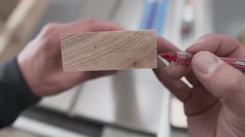
Bar: Cut a hardwood piece to the desired length of your clamp. Typically, a length of 24 to 36 inches is practical.
Jaws: Cut two pieces of hardwood for the jaws. These should be about 6 inches long, 2 inches wide, and 1 inch thick. The jaws can be adjusted according to your needs.
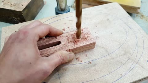
2. Drill Holes for the Threaded Rod
On each jaw, drill a hole slightly larger than the diameter of your threaded rod. Ensure the holes are aligned when the jaws are placed on the bar.
3. Prepare the Bar
If you want to prevent the jaws from sliding off the bar, drill a hole at one end of the bar and insert a bolt or dowel. This will act as a stop.
4. Assemble the Jaws
Insert the threaded rod through the holes in the jaws.
Secure the rod in place with nuts and washers on both sides of each jaw. You can use epoxy to secure the nuts for a stronger hold.
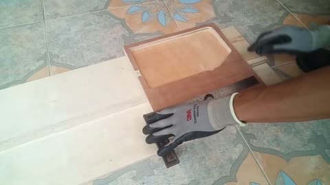
5. Attach the Jaws to the Bar
Position the jaws on the bar and mark
10
views
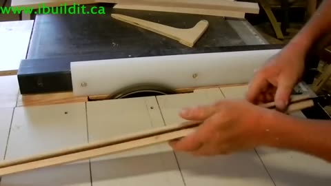
How To Make The Ultimate Box Joint Jig
Creating the ultimate box joint jig involves precision and attention to detail, ensuring that the jig is both versatile and easy to use. Here’s a detailed guide on how to make a high-quality box joint jig.
Materials and Tools Needed
Materials:
Plywood or MDF for the base and fence (3/4" thick is ideal)
Hardwood or MDF for the guide bars
Threaded rods, nuts, and washers (for adjustability)
Wood screws
Glue
T-track (optional, for added adjustability)
Knobs (for easy adjustments)
Tools:
Table saw or circular saw
Router with a straight bit
Drill and drill bits
Measuring tape or ruler
Square
Clamps
Sandpaper or sander
Chisel (optional, for fine adjustments)
Screwdriver
Steps to Make the Ultimate Box Joint Jig
1. Cut the Base and Fence
Base: Cut a piece of plywood or MDF to approximately 24” x 12”. This will be the base of the jig that slides along the table saw’s miter slots.
Fence: Cut another piece for the fence, about 3” to 4” high and the same length as the base.
2. Prepare the Guide Bars
Cut two strips of hardwood or MDF to fit snugly in the miter slots of your table saw. These should be the same length as the base.
Attach the guide bars to the underside of the base using screws and glue, ensuring they are parallel and fit smoothly into the miter slots.
3. Attach the Fence to the Base
Position the fence perpendicular to the guide bars and attach it to the base using screws and glue. Ensure it is square and securely fixed.
4. Create the Adjustable Index Pin
Index Pin: This pin will set the spacing for your box joints. Cut a piece of hardwood to the width of the desired finger (e.g., 1/4” or 1/2”) and about 2” long.
Slot for Index Pin: Cut a slot in the fence to accommodate the index pin. The slot should be slightly wider than the pin to allow for some adjustability.
Insert the index pin into the slot and secure it with a bolt, washer, and wing nut or knob for easy adjustment.
5. Add the Threaded Rod for Adjustability (Optional)
Drill a hole through the fence and base near the index pin slot.
Insert a threaded rod through the hole and secure it with nuts and washers on both sides. This rod allows you to fine-tune the position of the index pin.
6. Install a T-Track (Optional)
If you want more flexibility, install a T-track along the fence. This will allow you to adjust the position of the index pin easily by sliding it along the track.
7. Add a Clamping System
To hold your workpieces securely, add clamps to the fence. You can use T-track clamps or make custom clamps that attach to the fence with screws and knobs.
8. Test and Fine-Tune the Jig
Test the jig by making a few trial cuts. Adjust the index pin and the position of the fence as needed to ensure precise and even box joints.
Using the Box Joint Jig
Set the Index Pin: Adjust the index pin to the desired finger width.
Position the Workpiece: Place your workpiece against the fence and align it with the index pin.
Make the First Cut: Slide the jig along the table saw’s miter slots to make the first cut.
Index the Workpiece: Move the workpiece so that the first cut fits over the index pin.
Repeat: Make successive cuts, indexing the workpiece each time to create evenly spaced box joints.
By following these steps, you’ll create a highly functional and precise box joint jig that will enhance your woodworking projects. This jig can be adjusted for different finger widths and ensures consistent, tight-fitting joints every time.
5
views
Make These Clamps And Save Hundreds of Dollars Woodworking
Creating your own woodworking clamps can be a cost-effective way to save money while adding useful tools to your workshop. Here are a few types of clamps you can make yourself, along with instructions on how to build them:
1. Pipe Clamps
Materials:
Steel pipes (length of your choice)
Pipe clamp fixtures (available at hardware stores)
Rubber pads or scraps of leather (to protect workpieces)
Epoxy or strong adhesive (optional)
Tools:
Pipe cutter (if cutting pipes to length)
Wrench
Instructions:
Cut the Pipes: Cut steel pipes to the desired lengths if they aren't pre-cut.
Attach Clamp Fixtures: Screw the pipe clamp fixtures onto the ends of the pipes. These fixtures typically include a fixed jaw and a movable jaw.
Add Protective Pads: Attach rubber pads or scraps of leather to the clamp jaws using epoxy or adhesive to protect your workpieces from damage.
Test the Clamps: Test the clamps to ensure they tighten and loosen smoothly.
2. Bar Clamps
Materials:
Hardwood strips (e.g., oak or maple)
Threaded rods
Nuts and washers
Wood glue
Rubber pads or scraps of leather
Tools:
Saw (for cutting wood strips)
Drill and drill bits
Wrench
Clamps (for glue-up)
Instructions:
Cut the Hardwood Strips: Cut hardwood strips to the desired lengths for the bar clamps.
Drill Holes for Threaded Rods: Drill holes through the strips for the threaded rods. These holes should be slightly larger than the diameter of the rods.
Glue and Assemble: Glue pairs of strips together to form the bars of the clamps, ensuring the holes for the rods are aligned. Use temporary clamps to hold the pieces together while the glue dries.
Insert Threaded Rods: Insert the threaded rods through the holes and secure them with nuts and washers.
Attach Protective Pads: Attach rubber pads or scraps of leather to the clamp jaws to protect your workpieces.
Test the Clamps: Test the clamps to ensure they work correctly and adjust as needed.
3. Wooden Cam Clamps
Materials:
Hardwood (e.g., maple or birch)
Wooden dowels
Wood glue
Rubber pads or scraps of leather
Tools:
Saw (for cutting wood pieces)
Drill and drill bits
Sandpaper
Clamps (for glue-up)
Instructions:
Cut the Hardwood: Cut the hardwood into pieces for the clamp body and the movable jaw.
Drill Holes for Dowels: Drill holes in the clamp body and movable jaw for the wooden dowels. These dowels will act as the pivot and locking mechanism.
Assemble the Clamps: Glue and insert the dowels into the drilled holes, creating a pivot point for the movable jaw.
Shape the Cam: Cut and shape a piece of hardwood into a cam that will provide the clamping pressure. Attach this cam to the dowel on the movable jaw.
Attach Protective Pads: Attach rubber pads or scraps of leather to the clamp jaws to protect your workpieces.
Test the Clamps: Test the cam action to ensure it applies pressure effectively and adjust as needed.
Tips for Making Clamps:
Choose Quality Materials: Use strong, durable hardwoods and high-quality hardware to ensure the longevity of your clamps.
Precision: Measure and cut materials accurately to ensure the clamps work smoothly and hold securely.
Safety: Always wear appropriate safety gear and follow safety guidelines when using tools.
By making your own clamps, you can tailor them to your specific needs and save money that can be invested in other tools or materials for your woodworking projects.
11
views
Router Lift DIY _ Making a Router lift
Creating a DIY router lift can be a rewarding project, offering both the satisfaction of a custom-built tool and potential cost savings compared to commercial options. Here's a step-by-step guide to help you make a router lift.
Materials Needed:
Router (to be mounted)
Plywood or MDF (for base and carriage)
Threaded rod or lead screw (for lifting mechanism)
Bearings or bushings (for smooth operation)
Nuts and washers
Knobs or handles (for adjustment)
Aluminum or steel plates (for mounting hardware)
Screws, bolts, and other fasteners
Springs (optional, for counterbalance)
Tools Required:
Table saw or circular saw
Drill and bits
Jigsaw
Screwdriver
Wrench set
Measuring tape
Clamps
Square
Sandpaper or file
Step-by-Step Guide:
1. Design and Planning
Measure your router: Determine the size and mounting holes of your router to create a compatible lift.
Design the lift: Sketch a design for the lift mechanism, including the base plate, carriage, and lifting mechanism.
2. Base Plate
Cut the base plate: Cut a piece of plywood or MDF to fit your router table insert or the desired size.
Drill mounting holes: Drill holes to attach the router to the base plate, ensuring alignment with the router's mounting holes.
3. Carriage
Cut the carriage pieces: Cut pieces of plywood or MDF to form the carriage that will hold the router.
Assemble the carriage: Attach the carriage pieces together to create a sturdy structure that can move vertically.
4. Lifting Mechanism
Install threaded rod or lead screw: Secure a threaded rod or lead screw vertically to the base plate. This will be used to raise and lower the router.
Add bearings or bushings: Install bearings or bushings to ensure smooth movement of the carriage along the rod.
Attach nut to carriage: Fix a nut to the carriage that will travel along the threaded rod as it is turned.
5. Adjustment Knob or Handle
Attach handle to threaded rod: Install a handle or knob at the top of the threaded rod to facilitate easy adjustment.
Secure lifting mechanism: Ensure the lifting mechanism is stable and operates smoothly.
6. Final Assembly
Mount the router: Attach your router to the carriage using the previously drilled holes.
Attach the base plate: Secure the base plate to your router table or insert.
Test the mechanism: Operate the lift to ensure it raises and lowers the router smoothly and consistently.
7. Adjustments and Calibration
Fine-tune the mechanism: Make any necessary adjustments to ensure accurate and smooth operation.
Add safety features: Consider adding stops or locks to secure the router at a desired height.
Tips:
Material choice: Use sturdy, stable materials for the base and carriage to ensure durability and accuracy.
Precision: Take your time with measurements and assembly to ensure the lift operates smoothly.
Safety: Always prioritize safety when working with power tools and during the operation of your router lift.
Building a router lift involves precise measurement and careful assembly, but the end result is a customized tool that can enhance your woodworking projects. Good luck with your DIY router lift!
13
views
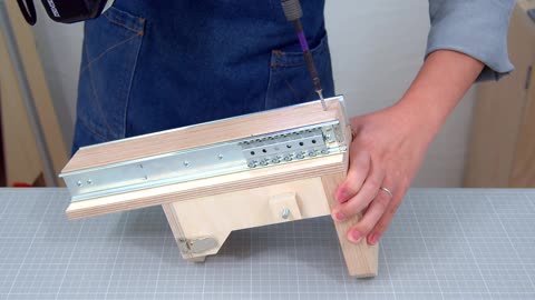
How To Make Wooden Full Extension Drawer Slides - Woodworking
Making wooden full extension drawer slides is a challenging yet rewarding woodworking project that requires precision and attention to detail. Here's a general overview of the process:
Materials and Tools Needed:
Hardwood lumber for the slides (e.g., maple, oak)
Plywood or hardwood for the drawer boxes
Measuring tape, pencil, and straight edge
Table saw or circular saw
Router with dado blade or straight bit
Drill and drill bits
Screws
Sandpaper or sanding block
Wood glue
Finish (e.g., stain, varnish, or paint)
Step-by-Step Instructions:
Measure the dimensions of your drawer openings and determine the desired length and width of your drawer slides.
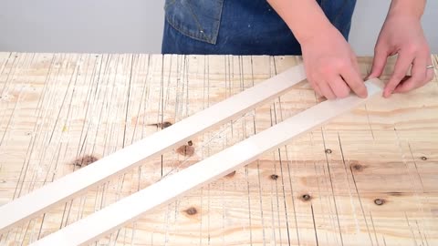
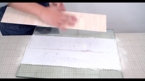
Cut the hardwood lumber into strips to create the drawer slides. The width of the strips should match the thickness of the drawer sides.
Use a router to create dadoes or slots along the length of the drawer slides. These dadoes will hold the drawer bottoms and allow for full extension.
Cut the plywood or hardwood into pieces to create the drawer boxes, ensuring they are sized to fit within the drawer openings.
Assemble the drawer boxes using wood glue and screws, making sure they are square and flush.
Attach the drawer slides to the sides of the drawer boxes using screws, ensuring they are aligned and level.
Install the drawer slides into the cabinet openings, positioning them to allow for full extension of the drawers.
Test the drawers to ensure they slide smoothly and extend fully without binding.
Sand the drawer slides and boxes to remove any rough edges and smooth out any imperfections.
Apply a finish of your choice to protect the wood and enhance its appearance.
By following these steps and taking your time to ensure accuracy, you can create custom wooden full extension drawer slides that add both functionality and beauty to your woodworking projects.
10
views
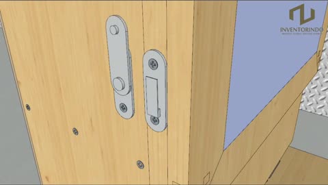
How To Make A Sliding Dovetail Joint on the Table Saw _ Woodworking
Creating a sliding dovetail joint on a table saw requires precision and careful attention to detail. Here's a step-by-step guide to making a sliding dovetail joint using a table saw:
Materials and Tools Needed:
Hardwood lumber for the joint components
Table saw with dado blade or router table with dovetail bit
Miter gauge or sled for guiding the workpiece
Dovetail jig (optional, but recommended for more precise cuts)
Measuring tape, pencil, and straight edge
Clamps
Chisel and mallet (for fine-tuning the fit)
Step-by-Step Instructions:
Prepare the workpieces: Cut the boards to the desired dimensions and mark the location of the dovetail joint on each piece. One board will have the dovetail "tail," and the other will have the dovetail "socket."
Set up the table saw: Install a dado blade on the table saw and adjust the height to match the thickness of the dovetail joint. Set the fence to position the dado blade at the correct distance from the blade.
Make test cuts: Use scrap pieces of wood to make test cuts and fine-tune the setup of the table saw. Make adjustments to the height and position of the dado blade as needed to achieve the desired fit for the joint.
Cut the dovetail sockets: Place the board that will receive the dovetail joint against the fence of the table saw and use a miter gauge or sled to guide it through the blade. Make multiple passes to remove material and create the dovetail socket. Take care to keep the workpiece flat against the table and fence to ensure straight and even cuts.
Cut the dovetail tails: Place the board that will form the dovetail joint on edge against the table saw fence and use the miter gauge or sled to guide it through the blade. Make multiple passes to remove material and create the dovetail tails. Again, keep the workpiece flat against the table and fence to ensure accuracy.
Dry-fit the joint: Test the fit of the dovetail joint by sliding the tail into the socket. The joint should be snug but not too tight. Use a chisel and mallet to fine-tune the fit if necessary.
Glue and assemble the joint: Apply wood glue to the mating surfaces of the joint and carefully assemble the pieces. Use clamps to hold the joint securely while the glue dries.
Sand and finish: Once the glue has dried, sand the joint smooth and apply a finish of your choice to protect the wood and enhance its appearance.
By following these steps and taking your time to ensure accuracy, you can create a strong and visually appealing sliding dovetail joint using a table saw.
27
views
DIY Crosscut Sled and Accessories Part 2_ T-Track Hold Down Clamps and Quick Clamp __ Woodworking
In this woodworking tutorial, we dive into the construction of essential accessories for a crosscut sled. Part 2 focuses on crafting T-track hold down clamps and quick clamps, integral tools for ensuring precision and safety in woodworking projects. These accessories offer versatility and convenience, allowing woodworkers to securely hold down materials during cutting operations. With detailed step-by-step instructions and practical tips, this video guides viewers through the process of creating these indispensable accessories, empowering them to enhance the functionality of their crosscut sled and elevate their woodworking skills. Whether you're a seasoned woodworker or a beginner looking to expand your toolkit, this DIY project provides valuable insights and hands-on experience to elevate your craft.
40
views
Making Wooden Knobs Mastering the Technique of Easy Shape and Size Adjustment with New Jigs
"Making Wooden Knobs: Mastering the Technique of Easy Shape and Size Adjustment with New Jigs DIY" by searching for it on the Y2mate website or a similar platform. Once you find the video, you can watch it to learn more about the technique of making wooden knobs and adjusting their shape and size with new jigs. If you have any specific questions about woodworking or making wooden knobs, feel free to ask!
2
views

Making Woodenobs Mastering the Technique of Easy Shape and Size Adjustment with New Jigs.
Crafting wooden knobs can be a fun and rewarding DIY project, especially when you learn new techniques and use jigs to streamline the process. Creating custom wooden knobs allows for personalization and adds a unique touch to furniture or woodworking projects. Enjoy mastering this technique and creating beautiful wooden knobs for your projects!
3
views
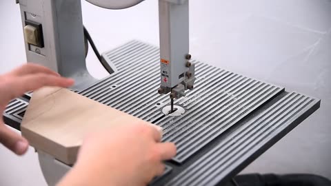
How to make Scroll Saw (Speed Control) 스크롤쏘(속도조절)
Making a scroll saw with speed control involves a bit of technical know-how and some electrical work. Here's a general guide on how you might approach it:
Materials needed:
DC motor: Look for a DC motor suitable for your project. The power and speed capabilities will depend on the size of the scroll saw you intend to build.
Speed controller: You'll need a speed controller that can handle the voltage and current requirements of your motor. This can be a purchased component or you can build one yourself using a PWM (Pulse Width Modulation) circuit.
Power supply: Depending on the voltage requirements of your motor and speed controller, you'll need an appropriate power supply.
Saw frame and blade: You'll need to construct or acquire a frame for your scroll saw, along with the appropriate blade for cutting wood or other materials.
Mounting hardware: Bolts, nuts, and brackets to securely mount the motor and other components to your saw frame.
Wiring and connectors: Electrical wire to connect the motor, speed controller, and power supply, along with appropriate connectors and terminals.
Steps:
Construct the saw frame: Design and build a frame that will hold the motor, blade, and other components securely. This could be made from wood, metal, or a combination of materials.
Mount the motor: Attach the motor to the frame using bolts, nuts, and brackets. Ensure that the motor is positioned correctly and securely.
Install the speed controller: Mount the speed controller to the frame in a convenient location. Connect the input terminals of the speed controller to the power supply and the output terminals to the motor.
Wire the components: Use electrical wire to connect the motor, speed controller, and power supply according to the wiring diagram provided with the speed controller.
Test the setup: Before fully assembling the scroll saw, test the motor and speed controller to ensure that everything is working correctly. Adjust the speed control to verify that the motor speed varies as expected.
Final assembly: Once you're satisfied with the functionality of the scroll saw, complete the assembly by attaching the blade and any other necessary components.
Fine-tuning: Fine-tune the speed control settings and blade tension to optimize performance for your specific cutting needs.
Safety precautions: Always follow safety guidelines when using power tools, including wearing appropriate safety gear such as goggles and hearing protection.
Please note that building a scroll saw with speed control requires electrical knowledge and skills, as well as an understanding of safety practices when working with power tools. If you're not comfortable with these aspects, it may be best to purchase a pre-made scroll saw with speed control instead.
스크롤쏘(속도조절)
스크롤 쏘(Scroll Saw)는 작은 곡선이나 복잡한 패턴을 따라 재료를 절단하는 데 사용되는 전기 톱입니다. 이를 속도 조절 가능한 스크롤 쏘로 만들기 위해서는 일부 전기적인 작업이 필요합니다. 여기에는 다음과 같은 단계가 포함될 수 있습니다:
모터 선택: 먼저 사용할 모터를 선택해야 합니다. 일반적으로 스크롤 쏘에는 속도를 조절할 수 있는 DC 모터가 사용됩니다.
속도 조절 장치 구매 또는 제작: 모터와 함께 사용할 속도 조절 장치를 구입하거나 직접 제작해야 합니다. 속도 조절 장치는 모터의 속도를 제어하기 위해 사용됩니다.
전원 공급 장치: 모터와 속도 조절 장치에 전원을 제공할 수 있는 적절한 전원 공급 장치가 필요합니다.
톱 프레임 및 날 조립: 스크롤 쏘의 프레임을 구성하고, 톱 날을 장착해야 합니다.
모터 및 속도 조절 장치 연결: 모터와 속도 조절 장치를 전원 공급 장치에 연결하고, 속도 조절 장치의 출력을 모터에 연결해야 합니다.
테스트 및 조정: 모터와 속도 조절 장치의 작동을 확인하고, 필요에 따라 속도를 조정하여 최적의 성능을 얻을 수 있도록 조정해야 합니다.
이러한 단계를 따라 직접 속도 조절 가능한 스크롤 쏘를 만들 수 있습니다. 다만, 이 작업은 전기적인 지식과 기술이 필요하며 안전에 주의해야 합니다. 만약 이러한 작업에 익숙하지 않다면, 사전에 제작된 속도 조절 가능한 스크롤 쏘를 구입하는
4
views

확장 가능한 목공용 원형톱 마이터 트랙 DIY│Extendable Circular Saw Maiter Satation
DIY 프로젝트에서는 확장 가능한 목공용 원형톱 마이터 트랙을 만들어 보겠습니다. 이 트랙은 원형톱을 사용하여 정확한 90도 및 각도 절단을 수행할 수 있는 편리한 솔루션을 제공합니다. 이 확장 가능한 트랙은 다양한 길이의 재료를 자를 수 있도록 설계되어 있으며, 마이터 족을 통해 정확한 각도 절단이 가능합니다. 이 프로젝트를 통해 자신만의 목공용 툴을 만들고 목재 작업을 더욱 쉽게 수행할 수 있습니다.
english
In this DIY project, we'll be creating an extendable circular saw miter track for woodworking. This track provides a convenient solution for making precise 90-degree and angled cuts using a circular saw. The extendable track is designed to accommodate materials of various lengths, and with the miter stops, precise angle cuts can be achieved. Through this project, you'll be able to create your own woodworking tool and make woodworking tasks easier.
6
views
diy simple circular saw track saw guide __ plywood version.
Materials Needed:
Plywood sheet (3/4 inch thick)
Circular saw
Straightedge or straight piece of lumber
Screws
Drill
Measuring tape
Pencil
Clamps
Instructions:
Measure and Cut Plywood:
Determine the desired length and width of your track saw guide. A standard size is 8 feet long and 6 inches wide.
Measure and mark the plywood sheet according to your dimensions.
Use a circular saw to cut the plywood to size. Make sure your cuts are straight and accurate.
Attach Straightedge:
Place the straightedge or a straight piece of lumber along one edge of the plywood. This will serve as the guide for your circular saw.
Align the straightedge precisely along the edge of the plywood and clamp it securely in place.
Align Saw and Cut Guide Slot:
Position your circular saw next to the straightedge on the plywood.
Adjust the saw's cutting depth to ensure it will cut through the plywood but not into the surface underneath.
Carefully run the saw along the straightedge, cutting a slot into the plywood. This slot will serve as the guide for your circular saw.
Secure Guide to Work Surface:
Once you've cut the guide slot, remove the clamps holding the straightedge in place.
Flip the plywood over so that the guide slot is facing downwards.
Position the guide on your work surface where you'll be making your cuts.
Secure the guide to the work surface using screws or clamps to prevent it from moving during use.
Test and Adjust:
Before making any cuts, test the guide with your circular saw to ensure it slides smoothly along the slot and produces straight cuts.
If necessary, make adjustments to the guide or the saw's settings to achieve the desired results.
Optional Enhancements:
To improve the durability and longevity of your track saw guide, consider adding strips of adhesive-backed measuring tape along the edge for easy measurement.
You can also attach additional pieces of plywood to the sides of the guide to create a wider cutting surface for larger workpieces.
By following these steps, you can create a simple yet effective circular saw track saw guide using plywood. This DIY solution will help you achieve accurate and straight cuts in your woodworking projects.
4
views
Amazing Benchtop Jointer - How to Make a Jointer - Rig System Part.3
Creating an amazing benchtop jointer as Part 3 of a rig system project can significantly enhance the precision and quality of your woodworking tasks. Here's how you can structure this segment:
Introduction:
Introduce Part 3 of the rig system project, focusing on the construction of a benchtop jointer.
Highlight the benefits of having a homemade jointer, including cost-effectiveness and customization options.
Materials Needed:
List the materials required for this part of the project, such as:
Plywood or MDF for the base and frame
Aluminum or steel rails for the jointer bed
Electric motor or hand-crank mechanism
Cutting blades or cutter heads
Screws, bolts, and nuts
Safety equipment (goggles, gloves, etc.)
Tools Needed:
Provide a list of tools necessary for the construction process, including:
Circular saw or jigsaw for cutting materials
Drill and drill bits for making holes
Screwdriver or wrench for assembly
Measuring tape and pencil for marking
Construction Steps:
Design and Layout:
Discuss the design considerations for the benchtop jointer, including size, bed length, and fence design.
Use sketches or diagrams to illustrate the layout and dimensions of the components.
Building the Base and Frame:
Cut the plywood or MDF according to the design specifications to create the base and frame of the jointer.
Assemble the base and frame using screws or bolts, ensuring stability and rigidity.
Installing the Jointer Bed:
Attach aluminum or steel rails to the base to serve as the jointer bed.
Ensure the rails are aligned parallel to each other and spaced appropriately for the cutting mechanism.
Mounting the Cutting Mechanism:
Install the electric motor or hand-crank mechanism to drive the cutting blades or cutter heads.
Position the cutting mechanism on the jointer bed, ensuring smooth and precise movement.
Adding Safety Features:
Incorporate safety features such as blade guards or emergency stop switches to prevent accidents during operation.
Safety Precautions:
Remind viewers to exercise caution when working with power tools and sharp objects.
Emphasize the importance of wearing appropriate safety gear, such as goggles and gloves, to prevent accidents or injuries.
Conclusion:
Summarize the key steps covered in Part 3 of the rig system project.
Encourage viewers to experiment with their own homemade jointers and share their experiences with the community.
By providing clear instructions and demonstrations, you can create an informative and engaging Part 3 video for your amazing benchtop jointer rig system project, inspiring viewers to explore new possibilities in their woodworking endeavors.
2
views
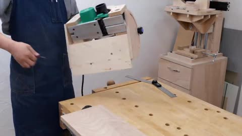
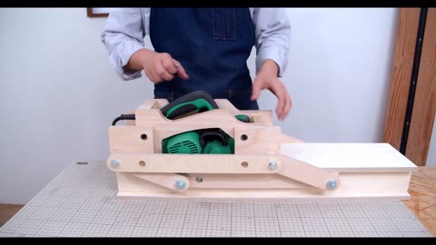
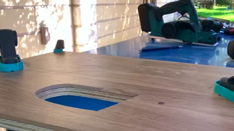
2in1 Using an Electric Hand Plane - Rig System Part.5
Creating a 2-in-1 setup using an electric hand plane as Part 5 of a rig system project can significantly enhance the versatility and functionality of your woodworking tools. Here's how you can structure this segment:
Introduction:
Introduce Part 5 of the rig system project, focusing on the integration of an electric hand plane into the existing setup.
Highlight the benefits of having a 2-in-1 system, including increased flexibility and efficiency in woodworking tasks.
Materials Needed:
List the materials required for this part of the project, such as:
Electric hand plane
Mounting brackets or adapters
Screws, bolts, and nuts
Safety equipment (goggles, gloves, etc.)
Tools Needed:
Provide a list of tools necessary for the installation process, including:
Drill and drill bits for making holes
Screwdriver or wrench for assembly
Measuring tape and pencil for marking
Installation Steps:
Design and Layout:
Discuss the design considerations for integrating the electric hand plane into the rig system.
Use sketches or diagrams to illustrate the layout and placement of the hand plane within the setup.
Mounting the Hand Plane:
Attach mounting brackets or adapters to the rig system to accommodate the electric hand plane.
Ensure the hand plane is securely fastened and aligned with the other components of the setup.
Adjustment and Alignment:
Fine-tune the positioning of the hand plane to ensure optimal performance and compatibility with the rig system.
Make any necessary adjustments to align the blades or cutting surface with the workpiece.
Testing and Calibration:
Test the functionality of the 2-in-1 setup, including the electric hand plane and any other components integrated into the rig system.
Make any final adjustments or calibrations to ensure smooth operation and accurate results.
Safety Precautions:
Remind viewers to exercise caution when working with power tools and sharp objects.
Emphasize the importance of wearing appropriate safety gear, such as goggles and gloves, to prevent accidents or injuries.
Conclusion:
Summarize the key steps covered in Part 5 of the rig system project.
Encourage viewers to experiment with their own 2-in-1 setups and share their experiences with the community.
By providing clear instructions and demonstrations, you can create an informative and engaging Part 5 video for your electric hand plane rig system project, inspiring viewers to explore new possibilities in their woodworking endeavors.
7
views
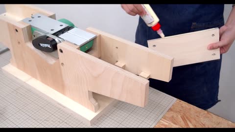
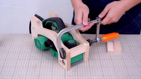
Electric plane angle adjustment jig - Rig System Part.4
For Part 4 of your electric plane angle adjustment jig rig system project, you could focus on the construction and installation of the angle adjustment mechanism. Here's a rough outline for the video:
Introduction:
Briefly recap the purpose of the project and the progress made in previous parts.
Introduce the focus of Part 4: building the angle adjustment mechanism for the electric plane.
Materials Needed:
List the materials required for this part of the project, such as:
Angle brackets or hinges
Screws, bolts, and nuts
Wing nuts or knobs for adjusting
Drill and drill bits
Measuring tape and pencil
Tools Needed:
Provide a list of tools necessary for the construction process, including:
Drill and drill bits for making holes
Screwdriver or wrench for assembly
Saw (if modifications are needed)
Measuring tape and pencil for marking
Construction Steps:
Designing the Angle Adjustment Mechanism:
Discuss the design considerations for the mechanism, such as range of adjustment and ease of use.
Sketch out the design and explain how it will function.
Preparing the Components:
Cut or modify the angle brackets or hinges as needed to fit the dimensions of the electric plane and the rig system.
Installing the Mechanism:
Attach the angle brackets or hinges to the base of the rig system using screws or bolts.
Ensure that the mechanism is securely mounted and allows for smooth adjustment of the angle.
Adding Adjustment Controls:
Install wing nuts or knobs on the angle brackets or hinges to provide a means of adjusting the angle of the electric plane.
Test the adjustment mechanism to ensure that it functions properly and allows for precise angle control.
Safety Precautions:
Remind viewers to exercise caution when working with power tools and sharp materials.
Emphasize the importance of following safety guidelines and manufacturer instructions throughout the construction process.
Conclusion:
Summarize the key steps covered in Part 4 of the project.
Preview the next part of the series, where you will demonstrate the completed electric plane angle adjustment jig in action.
By following this outline, you can create an informative and engaging Part 4 video for your electric plane angle adjustment jig rig system project.
12
views
Planer slide jig - Rig System Part.1
Creating a planer slide jig or rig system can be an efficient way to achieve precise and consistent results when working with a planer. Here's an outline for Part 1 of such a project:
Introduction:
Briefly introduce the purpose of the planer slide jig and its benefits for woodworking projects.
Mention the focus of Part 1, which could be designing and constructing the base or framework of the rig system.
Materials Needed:
List the materials required for this part of the project, such as:
Sturdy plywood or MDF for the base
Aluminum or steel rails for the sliding mechanism
Screws, bolts, and nuts
Clamps or brackets for securing the planer
Safety equipment (goggles, gloves, etc.)
Tools Needed:
Provide a list of tools necessary for the construction process, including:
Circular saw or jigsaw for cutting materials
Drill and drill bits for making holes
Screwdriver or wrench for assembly
Measuring tape and pencil for marking
Construction Steps:
Design and Layout:
Discuss the design considerations for the base or framework, such as size, shape, and stability.
Use sketches or diagrams to illustrate the layout and dimensions of the components.
Cutting the Base:
Measure and mark the plywood or MDF according to the design specifications.
Use a circular saw or jigsaw to cut the base to the desired size and shape.
Assembling the Rails:
Attach the aluminum or steel rails to the base using screws or bolts.
Ensure the rails are aligned parallel to each other and spaced appropriately for the planer to slide smoothly.
Securing the Planer:
Install clamps or brackets on the base to secure the planer in place.
Consider adding adjustable features to accommodate different sizes or models of planers.
Safety Precautions:
Remind viewers to wear appropriate safety gear, such as goggles and gloves, when working with power tools and sharp materials.
Emphasize the importance of following safety guidelines and manufacturer instructions throughout the construction process.
Conclusion:
Summarize the key steps covered in Part 1 of the project.
Encourage viewers to stay tuned for Part 2, where additional components or features of the planer slide jig will be discussed.
By following these guidelines, you can create an informative and engaging Part 1 video for your planer slide jig project.
8
views
Parallel link Planer jig - Rig System Part.2
For Part 2 of your parallel link planer jig rig system project, you can focus on constructing the moving parts and fine-tuning the alignment for precise planing results. Here's a breakdown of what you can cover:
Introduction:
Recap briefly on what was covered in Part 1, which likely included designing and building the base or framework for the jig rig system.
Introduce the focus of Part 2, which is to create the moving parts and ensure smooth operation.
Materials and Tools:
Provide a list of additional materials and tools needed for this part of the project, such as:
Metal or wooden bars for the parallel links
Screws, bolts, and washers
Hinges or pivots for connecting the links
Leveling feet or adjustable supports
Measuring tools for precise alignment
Construction Steps:
Building the Parallel Links:
Cut the metal or wooden bars to the desired length for the parallel links.
Attach hinges or pivots to one end of each link to allow for movement.
Mounting the Links:
Attach the parallel links to the base of the jig rig system using screws, bolts, and washers.
Ensure the links are mounted securely and aligned parallel to each other and perpendicular to the planer.
Connecting the Planer:
Install brackets or mounts on the parallel links to secure the planer in place.
Test the movement of the planer along the parallel links to ensure smooth sliding motion.
Fine-Tuning Alignment:
Use leveling feet or adjustable supports to fine-tune the alignment of the planer.
Check for any misalignment or unevenness and make adjustments as needed to achieve precise planing results.
Testing and Adjustment:
Conduct test runs with the planer to verify the functionality and performance of the jig rig system.
Make any necessary adjustments to the parallel links, mounts, or alignment to optimize the operation of the planer.
Safety Precautions:
Remind viewers to prioritize safety when working with power tools and heavy machinery.
Emphasize the importance of proper assembly and alignment to prevent accidents and ensure accurate planing.
Conclusion:
Summarize the key steps covered in Part 2 of the project.
Encourage viewers to apply the techniques learned to their own woodworking projects and stay tuned for future tutorials.
By following these guidelines, you can create an informative and engaging Part 2 video for your parallel link planer jig rig system project, providing viewers with the knowledge and skills to build and optimize their own jig rig systems for precise planing.
28
views
MESA CASERA PORTÁTIL con cepillo canteador con 👉 ( AMORTIGUACIÓN )
MESA CASERA PORTÁTIL con cepillo canteador con 👉 ( AMORTIGUACIÓN )
ChatGPT
Crear una mesa casera portátil con un cepillo canteador y amortiguación puede ser un proyecto útil para trabajos de carpintería donde se requiera movilidad y estabilidad. Aquí tienes una guía básica para hacerlo:
Materiales Necesarios:
Tablero de madera contrachapada o MDF para la base y la superficie de trabajo
Cepillo canteador eléctrico
Tornillos o clavos
Amortiguadores de goma o resortes
Bisagras
Manija o asa de transporte
Almohadillas antideslizantes
Herramientas eléctricas y manuales: taladro, sierra, destornillador, etc.
Equipo de protección personal: gafas de seguridad, guantes, etc.
Pasos:
Diseño de la Mesa: Diseña el tamaño y la forma de la mesa portátil según tus necesidades y el espacio disponible. Asegúrate de incluir una sección para montar el cepillo canteador y espacio para almacenar los amortiguadores.
Construcción de la Base: Corta y ensambla el tablero de madera contrachapada o MDF para crear la base de la mesa. Refuerza las esquinas y los bordes para mayor resistencia y durabilidad.
Montaje del Cepillo Canteador: Fija el cepillo canteador a la mesa utilizando tornillos o abrazaderas. Asegúrate de que esté bien sujeto y nivelado para un rendimiento óptimo.
Instalación de los Amortiguadores: Coloca los amortiguadores de goma o resortes en la parte inferior de la mesa para amortiguar el impacto y reducir la vibración durante el uso del cepillo canteador.
Añadir Bisagras y Manija: Instala bisagras en un extremo de la mesa para que pueda plegarse y transportarse fácilmente. Agrega una manija o asa de transporte en el lado opuesto para mayor comodidad.
Aplicación de Almohadillas Antideslizantes: Pegue almohadillas antideslizantes en la parte inferior de la mesa para evitar que se deslice o se mueva durante el uso.
Pruebas y Ajustes: Una vez que la mesa esté ensamblada, realiza pruebas para asegurarte de que el cepillo canteador funcione correctamente y de que la mesa sea estable y portátil. Realiza los ajustes necesarios según sea necesario.
Con estos pasos, puedes construir tu propia mesa casera portátil con un cepillo canteador y amortiguación, lo que te brindará un espacio de trabajo conveniente y móvil para tus proyectos de carpintería. Asegúrate de seguir las medidas de seguridad adecuadas durante la construcción y el uso de la mesa.
12
views
Making Sliding Angle Grinder Stand _ DIY Sliding Angle Grinder Jig
reating a sliding angle grinder stand or jig can be a useful DIY project for woodworking or metalworking tasks that require precision cutting. Here's a basic guide to making one:
Materials Needed:
Angle grinder
Plywood or MDF board
Metal rails or drawer slides
Screws or bolts
L-brackets
Clamps
Safety goggles and gloves
Tools Needed:
Drill
Screwdriver or wrench
Saw (circular saw or jigsaw)
Measuring tape
Pencil
Steps:
Measure and Cut the Base: Begin by measuring and cutting a sturdy base for your sliding angle grinder stand from plywood or MDF board. The size of the base will depend on the dimensions of your angle grinder and the intended use of the jig.
Attach Rails or Drawer Slides: Attach metal rails or drawer slides to the underside of the base using screws or bolts. These will serve as the sliding mechanism for the angle grinder.
Mount the Angle Grinder: Secure the angle grinder to the base of the sliding mechanism using clamps or L-brackets. Make sure the grinder is positioned securely and can slide smoothly along the rails.
Test the Sliding Action: Slide the angle grinder back and forth along the rails to ensure smooth movement and stability. Make any necessary adjustments to the mounting or sliding mechanism as needed.
Secure the Grinder Handle: If desired, you can attach a handle or grip to the angle grinder to make it easier to maneuver while using the sliding jig.
Safety Precautions: Always wear safety goggles and gloves when operating power tools like angle grinders. Make sure the sliding jig is securely anchored to a stable work surface to prevent accidents.
Test and Fine-Tune: Once the sliding angle grinder stand is assembled, test it out on scrap materials to ensure it performs as expected. Make any final adjustments or modifications as needed to achieve the desired results.
By following these steps, you can create a DIY sliding angle grinder stand or jig that provides stability and precision for your cutting tasks. Remember to prioritize safety and take your time to ensure proper assembly and functionality.
16
views
HOW TO MAKE A FOLDING TABLE WITH CABINET
Creating a folding table with a cabinet involves some woodworking skills and tools. Here's a general guide to help you through the process:
Materials Needed:
Wood (plywood or solid wood boards)
Cabinet hinges
Screws
Wood glue
Cabinet handles/knobs
Sandpaper
Wood finish/paint
Folding table legs
Measuring tape
Saw (circular saw or table saw)
Drill
Screwdriver
Clamps
Steps:
1. Design Planning:
Decide on the dimensions of your folding table and cabinet based on your available space and needs.
Sketch out a plan including the table size, cabinet size, and how they will fold together.
2. Cutting the Wood:
Measure and cut the pieces for the tabletop, cabinet, and any shelves or compartments within the cabinet.
Ensure the cuts are precise for a neat and sturdy construction.
3. Assembling the Cabinet:
Assemble the sides, top, bottom, and back of the cabinet using wood glue and screws.
Attach the cabinet hinges to one side of the cabinet door and to the corresponding side of the cabinet body.
4. Installing the Cabinet:
Decide where you want the cabinet to be positioned under the table.
Attach the other half of the cabinet hinges to the underside of the tabletop and align them with the hinges on the cabinet door.
Ensure the hinges are properly aligned so the cabinet door can open and close smoothly.
5. Finishing:
Sand all the wood surfaces to smooth out any rough edges.
Apply wood finish or paint according to your preference. Let it dry completely.
6. Attaching the Folding Table Legs:
Measure and mark the positions for attaching the folding table legs.
Use screws to securely attach the folding table legs to the underside of the tabletop.
7. Adding Hardware:
Install cabinet handles/knobs on the cabinet door for easy opening and closing.
8. Testing:
Once everything is assembled and finished, test the folding mechanism to ensure it works smoothly and the table is stable when unfolded.
9. Final Touches:
Make any necessary adjustments or fixes.
Clean up any excess glue or marks.
Safety Tips:
Always wear appropriate safety gear like goggles and gloves when working with wood and power tools.
Follow the manufacturer's instructions for tools and equipment.
Work in a well-ventilated area when using wood finish or paint.
With careful planning and execution, you can create a functional and space-saving folding table with a cabinet that suits your
26
views