

A Message for Apprentices - DON'T DO THIS
Join this channel to get access to perks:
https://www.youtube.com/channel/UCB3jUEyCLRbCw7QED0vnXYg/join
🤘⚡️MEMBERSHIP⚡️🤘
JOIN ELECTRICIAN U - become a member and get:
FREE Continuing Education every year
FREE Practice Exams
FREE Monthly Video Courses
FREE Weekly Live Instructor-Led Classes
FREE Monthly Educational Newsletter
Premium Members-Only Content
Private Discord Channel
Monthly Members-Only Discord Chats
Sign up here --- https://www.electricianu.com/electrician-u-membership/
🎧🎹MUSIC AND VIDEO:🎹🎧
https://www.facebook.com/descantmv
🎬✍️ART AND ILLUSTRATION:✍️🎬
https://www.daverussoart.com
#electrician #electrical #electricity
288
views
1
comment
ChatGPT - 60Hz vs 50Hz
Join this channel to get access to perks:
https://www.youtube.com/channel/UCB3jUEyCLRbCw7QED0vnXYg/join
🤘⚡️MEMBERSHIP⚡️🤘
JOIN ELECTRICIAN U - become a member and get:
FREE Continuing Education every year
FREE Practice Exams
FREE Monthly Video Courses
FREE Weekly Live Instructor-Led Classes
FREE Monthly Educational Newsletter
Premium Members-Only Content
Private Discord Channel
Monthly Members-Only Discord Chats
Sign up here --- https://www.electricianu.com/electrician-u-membership/
🎧🎹MUSIC AND VIDEO:🎹🎧
https://www.facebook.com/descantmv
🎬✍️ART AND ILLUSTRATION:✍️🎬
https://www.daverussoart.com
#electrician #electrical #electricity
947
views
Is Electricity Stored in Batteries? Common Misconceptions
Join this channel to get access to perks:
https://www.youtube.com/channel/UCB3jUEyCLRbCw7QED0vnXYg/join
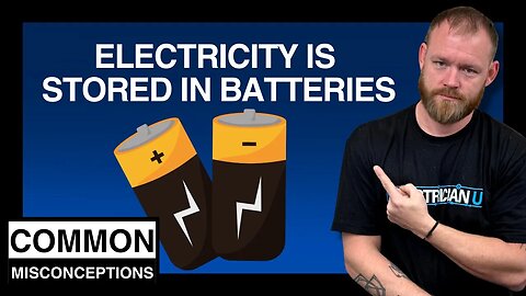
Batteries are in many of the items we use on a daily basis. And why not? It allows us to be mobile without having to be hindered with miles of extension cords connecting our equipment to a power source. But is electricity actually stored IN a battery? In today’s episode of Electrician U, Dustin speaks about how a battery works.
🤘⚡️MEMBERSHIP⚡️🤘
JOIN ELECTRICIAN U - become a member and get:
FREE Continuing Education every year
FREE Practice Exams
FREE Monthly Video Courses
FREE Weekly Live Instructor-Led Classes
FREE Monthly Educational Newsletter
Premium Members-Only Content
Private Discord Channel
Monthly Members-Only Discord Chats
Sign up here --- https://www.electricianu.com/electrician-u-membership/
🎧🎹MUSIC AND VIDEO:🎹🎧
https://www.facebook.com/descantmv
🎬✍️ART AND ILLUSTRATION:✍️🎬
https://www.daverussoart.com
To better understand what a battery is, let us define what electricity is. Electricity is a function of an interaction of charged particles that we can use EMF (electromotive force) to move current through a conductor. A battery on the other hand is a chemical storage device that doesn’t generate electricity until conductors are hooked up to it. And even then, the electricity is EXTERNAL to the battery, not within it. No conductors, no current flow!
There are many types of batteries- Lead Acid, Nickel Cadmium, Lithium Ion, and more. For the purposes of this discussion, we will be discussing a Lead Acid battery. This type of battery is a container that houses sulfuric acid (H2SO4). It also has 2 lead electrodes in it- 1 Anode and 1 Cathode. One of these lead electrodes has a coating of Lead Dioxide on it that attracts the charges while the other repels them.
When an external power source is introduced (a battery charger) to the battery, a chemical reaction happens, and the sulfuric acid starts to change. The SO4 transfers to the lead electrodes (positive to one, negative to the other) leaving H2O2 as the solution. The leads now become PBSO4 and are positively and negatively charged). At this point if conductors are added to the battery, one on each of the positive and negative terminals, along with a load, electrons will flow through them. But this is all EXTERNAL to the battery itself, not INTERNAL.
Energy itself must be transferred from one type to another to be useful. Take a power generation station. Some type of mechanical energy (a generator) spins on one end and is transferred overhead (as electrical energy) to a building. However, electrical energy isn’t useful until we transfer it into something useful to us. Maybe its light energy (light fixtures) or heat energy (a toaster or a heater).
So, as we can see, batteries don’t really STORE electricity, but rather store CHEMICALS. When an external source of power is applied to the battery, a chemical reaction occurs, positively and negatively charged particles are transferred to their respective electrodes and are discharged through the EXTERNAL conductors when hooked up to these electrodes!
We hope this has been helpful in understanding what a battery is and how it works. Is there a topic you would like to see discussed here on Electrician U? Leave us a comment in the comments section and let us know. Please continue to follow Dustin Stelzer and Electrician U as we are constantly updating our content to assist our followers in becoming the best electricians that they can be.
#electrician #electrical #is #electricity #stored #in #batteries #common #misconceptions
1.26K
views
1
comment

Blueprint Symbols
Join this channel to get access to perks:
https://www.youtube.com/channel/UCB3jUEyCLRbCw7QED0vnXYg/join
🤘⚡️MEMBERSHIP⚡️🤘
JOIN ELECTRICIAN U - become a member and get:
FREE Continuing Education every year
FREE Practice Exams
FREE Monthly Video Courses
FREE Weekly Live Instructor-Led Classes
FREE Monthly Educational Newsletter
Premium Members-Only Content
Private Discord Channel
Monthly Members-Only Discord Chats
Sign up here --- https://www.electricianu.com/electrician-u-membership/
🎧🎹MUSIC AND VIDEO:🎹🎧
https://www.facebook.com/descantmv
🎬✍️ART AND ILLUSTRATION:✍️🎬
https://www.daverussoart.com
#electrician #electrical #electricity
1.07K
views
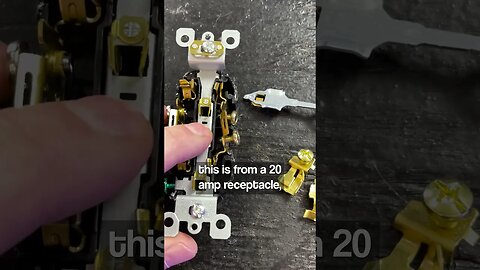
What's Inside a Receptacle
Join this channel to get access to perks:
https://www.youtube.com/channel/UCB3jUEyCLRbCw7QED0vnXYg/join
🤘⚡️MEMBERSHIP⚡️🤘
JOIN ELECTRICIAN U - become a member and get:
FREE Continuing Education every year
FREE Practice Exams
FREE Monthly Video Courses
FREE Weekly Live Instructor-Led Classes
FREE Monthly Educational Newsletter
Premium Members-Only Content
Private Discord Channel
Monthly Members-Only Discord Chats
Sign up here --- https://www.electricianu.com/electrician-u-membership/
🎧🎹MUSIC AND VIDEO:🎹🎧
https://www.facebook.com/descantmv
🎬✍️ART AND ILLUSTRATION:✍️🎬
https://www.daverussoart.com
#electrician #electrical #electricity
973
views

Blueprints Deciphered: How to Read Residential Plans (For Electricians)
Join this channel to get access to perks:
https://www.youtube.com/channel/UCB3jUEyCLRbCw7QED0vnXYg/join
Most of us in the industry know that in order for us to build something, we must have blueprints to understand exactly WHAT is needed. If it weren’t for those drawings, the framer, concrete contractors, the plumbers, even us electrical contractors wouldn’t know what or how to build it. But knowing HOW to interpret what is on those blueprints is an art in itself. In today’s episode of Electrician U, Dustin explains how to read and understand what is on a residential set of drawings.
🤘⚡️MEMBERSHIP⚡️🤘
JOIN ELECTRICIAN U - become a member and get:
FREE Continuing Education every year
FREE Practice Exams
FREE Monthly Video Courses
FREE Weekly Live Instructor-Led Classes
FREE Monthly Educational Newsletter
Premium Members-Only Content
Private Discord Channel
Monthly Members-Only Discord Chats
Sign up here --- https://www.electricianu.com/electrician-u-membership/
🎧🎹MUSIC AND VIDEO:🎹🎧
https://www.facebook.com/descantmv
🎬✍️ART AND ILLUSTRATION:✍️🎬
https://www.daverussoart.com
For most residential drawings, they will usually always be an “A” set of drawings. This stands for an Architectural set. Commercial drawings usually have the full complement (Architectural, Structural, Mechanical, Electrical, Plumbing, etc.). This is because in a residence, the architect is the one who draws it, and the architectural components are the most prominent features. Sets of drawings for different buildings will be different in the way they look. So, what is on one set of drawings won’t be the same for the next building.
The first sheet of a residential set of drawings shows an overall of the lot itself- the house, trees, pool (if one is being installed), etc. It will also have an address and/or a map, which can be very useful when coordinating getting manpower and deliveries to the site. It may also have important details regarding trees- to have us stay away from them when installing underground so as not to disturb the root ball or have the wiring destroyed years down the road as the tree grows.
The architectural details portion of the drawings will take up the most sheets. If it is an existing residence, there may be a Demo plan. This is very helpful in understanding which components of the building are being removed and which ones are staying/being added to or changed. There will be Elevation drawings- both interior and exterior. These show what the building will look like if you are facing a particular wall. The exterior will show the different siding types- whether its stone or siding. Interior elevations will show the wall covering materials/bookcases/cabinets- super useful to the electrician as it will show you WHERE/HEIGHTS to rough in for things like sconces or receptacles above the counter.
If there are electrical detail sheets, that is a huge plus! Not every set of residential drawing has these- usually only the larger residences. Smaller houses or track type homes may require the electrician to do the full layout and figure out what goes where. If the electrical sheets are present, look at the legend- usually the first sheet in the electrical series. It will delineate the different types of fixtures/switches/receptacles. The lighting fixtures will usually be linked together with an arc line showing which fixtures are to be linked together under the same switch leg. It will also show you the different fixtures. So you know whether it is a can light or a chandelier (and what type of box to install) and rough it in appropriately. The power set will tell you whether it’s a single receptacle or a quad and will also usually tell you if it’s above counter or below (you will still need to refer to the architectural elevations to figure out HOW HIGH to rough the box in.
Homeruns are usually left up to the installing electrician to figure out which string will be receiving the homerun cable itself. Mark these on the drawings (usually the closest to the panel to cut down on length). It is also helpful to mark off as you get homeruns/boxes/interconnecting wiring installed so you know what’s still left to do. Just make sure you make the markings in a way that you and everyone working with you understands so mistakes are lessened.
We hope this has been helpful in understanding how to read a set of residential drawings. Is there a topic you would like to see discussed here on Electrician U? Leave us a comment in the comments section and let us know. Please continue to follow Dustin Stelzer and Electrician U as we are constantly updating our content to assist our followers in becoming the best electricians that they can be.
#electrician #electrical #electricity #blueprints #deciphered #how #to #read #residential #plans
1.4K
views
3
comments

Which Codebook Should I Study? Electrical Code NEC 2023, 2020, 2017?
Join this channel to get access to perks:
https://www.youtube.com/channel/UCB3jUEyCLRbCw7QED0vnXYg/join
The NEC (National Electrical Code) has been around for some time. And for as long as most of us can remember, it goes through revisions and every 3 years a new one comes out! so, which version of the NEC should we be using? In today’s episode of Electrician U, Dustin explains the nuances of which codebook to use.
🤘⚡️MEMBERSHIP⚡️🤘
JOIN ELECTRICIAN U - become a member and get:
FREE Continuing Education every year
FREE Practice Exams
FREE Monthly Video Courses
FREE Weekly Live Instructor-Led Classes
FREE Monthly Educational Newsletter
Premium Members-Only Content
Private Discord Channel
Monthly Members-Only Discord Chats
Sign up here --- https://www.electricianu.com/electrician-u-membership/
🎧🎹MUSIC AND VIDEO:🎹🎧
https://www.facebook.com/descantmv
🎬✍️ART AND ILLUSTRATION:✍️🎬
https://www.daverussoart.com
The easiest explanation is to check with your local AHJ (Authority Having Jurisdiction- usually the city you are working in). Get hold of the inspection department/inspectors or even poll other TRUSTED electricians working in the area and ask! While nationally we may be required to use the current version of the NEC, many municipalities are still inspecting on the previous version. There are some municipalities that are several versions behind. And just because one city that you perform work in that uses the previous version, doesn’t mean that another city 5 miles down the road isn’t using a different one! Keep a current list of which municipalities are using what versions so you always have the pertinent information before performing work in any given area.
While the above explanation is for WORK performed, another would be for a journeyman’s license or masters license exams. This is where many electricians get frustrated. You have been installing on the 2020 code let’s say and go to take your exam only to find out they will be testing on the current 2023 code! Now you must learn on a completely new code cycle, and usually with not a lot of time to do so. Same as with the work area aspect, check with the place where you will be taking your exam and see which version they will be testing on. It will usually be on the CURRENT version of the NEC but check to make sure. And do this when you are thinking about getting ready to take your exam- don’t wait until the last minute!
The code changes every 3 years and new versions are issued. Industry changes, new equipment and materials are added, while some things become obsolete. So, it makes sense to revise things to keep current. Some changes are minor- small word type changes or punctuation. Some are logistical type changes- articles moved from one place to another. New definitions may be added or removed. While some changes are rather major- new articles are added or removed. Some articles are completely rewritten! Take article 242 (Over Voltage) that covers Surge Protection Devices for example. While it is in the 2020 & 2023 versions of the NEC, you won’t find it in the 2017 or earlier versions of the NEC. But it is an article that electricians use frequently when dealing with services and panels.
Another great resource is the Handbook. This is an invaluable study guide to use to understand the NEC. While it has the code verbiage within it, it looks much different than a standard codebook. Almost every article has pictures and additional wording in it that makes some of the more difficult articles much easier to understand and interpret. A word of caution here- this should be used as an ADDITION to the codebook, not a direct replacement. Most testing agencies will NOT let you bring in your handbook to test with and will only allow the codebook! So, if you are planning on taking your exam, I would strongly recommend that you use the handbook sparingly, so as not to get too used to it as you will not be allowed to reference it during your exam.
We hope this has been an insightful look into which version of the NEC you should be using. Is there a topic you would like to see discussed here on Electrician U? Leave us a comment in the comments section and let us know. Please continue to follow Dustin Stelzer and Electrician U as we are constantly updating our content to assist our followers in becoming the best electricians that they can be.
#electrician #electrical #electricity #nec #codebook #national #electric #code
886
views

Common Misconception: Do Breakers Put Out Power???
Join this channel to get access to perks:
https://www.youtube.com/channel/UCB3jUEyCLRbCw7QED0vnXYg/join
Have you ever wondered HOW breakers actually put out power? Interesting fact is that they don’t actually put out power and this is a common misconception among non-electricians. In today’s episode of Electrician U, Dustin talks about what a breakers function is.
🤘⚡️MEMBERSHIP⚡️🤘
JOIN ELECTRICIAN U - become a member and get:
FREE Continuing Education every year
FREE Practice Exams
FREE Monthly Video Courses
FREE Weekly Live Instructor-Led Classes
FREE Monthly Educational Newsletter
Premium Members-Only Content
Private Discord Channel
Monthly Members-Only Discord Chats
Sign up here --- https://www.electricianu.com/electrician-u-membership/
🎧🎹MUSIC AND VIDEO:🎹🎧
https://www.facebook.com/descantmv
🎬✍️ART AND ILLUSTRATION:✍️🎬
https://www.daverussoart.com
One of the larger misconceptions in the electrical industry (usually made by non-electricians or brand-new apprentices) is that a breaker will PUT OUT power. So, say a 20-amp breaker will put out 20 amps worth of current. In actuality, a breaker is a safety device with 2 primary functions. To LIMIT the amount of current allowed to pass through it, and to have the ability to shut whatever is on the LOAD side of the breaker OFF. But how does a breaker accomplish these 2 goals?
First, let’s talk about the overload function of a breaker. This function is the THERMAL portion of a breakers design. Breakers are designed to trip when the load becomes greater than its rating. So, a 20-amp breaker will trip when the load attached to it becomes greater than 20 amps, sort of. Most breakers are designed to trip (with the overload function) at 100-130% of their rated value. In-rush of a motor starting is one of the reasons why they are built not to trip at exactly their rated values. When a motor (or any load really) is attempting to first start up (from a dead stop), it will generally pull more amperage for a short period of time, as it is struggling to get moving from a nonmoving state. This will calm down within a few seconds (usually!) and will be within its normal range. If breakers weren’t designed to allow for this, then we would have to install larger amperage breakers and wouldn’t be able to protect the load at the values we need to and would run the risk of damaging equipment or overloading circuit conductors.
There is another major portion of a breaker’s design that protects against short circuits. This is accomplished by the magnetic trip of a breaker. The values of this function are much higher than the overload functions values and are in the 200-300% of the breakers listed amperage. Some breakers are even designed with adjustable magnetic trips. The reasoning behind the higher amperage rating of this function is that there is a considerably higher amperage available in a short circuit condition, as the loads resistance is basically removed from the equation.
So, as we can see, a breaker’s primary functions are to protect the equipment/conductors attached to it and don’t really put out power, but rather control how much current is allowed to flow through it. We hope this has been an insightful look into a breaker’s function and how they operate. Is there a topic you would like to see discussed here on Electrician U? Leave us a comment in the comments section and let us know. Please continue to follow Dustin Stelzer and Electrician U as we are constantly updating our content to assist our followers in becoming the best electricians that they can be.
#electrician #electrical #electricity #common #misconceptions #do #breakers #put #out #power
1.18K
views
1
comment
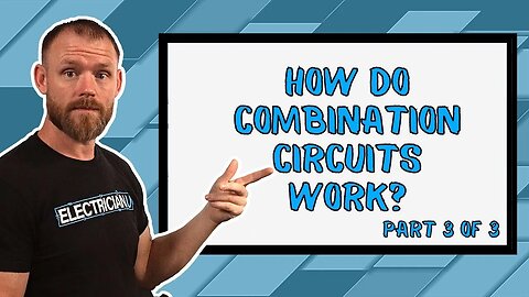
Let's Talk About COMBINATION Circuits: Voltage, Current, Resistance, and Power
Join this channel to get access to perks:
https://www.youtube.com/channel/UCB3jUEyCLRbCw7QED0vnXYg/join
We have talked about series and parallel circuits. But have you ever wondered how a series circuit works or what it even is? In today’s episode of Electrician U, Dustin covers part 3 of our topic on circuits- Combination Circuits!
🤘⚡️MEMBERSHIP⚡️🤘
JOIN ELECTRICIAN U - become a member and get:
FREE Continuing Education every year
FREE Practice Exams
FREE Monthly Video Courses
FREE Weekly Live Instructor-Led Classes
FREE Monthly Educational Newsletter
Premium Members-Only Content
Private Discord Channel
Monthly Members-Only Discord Chats
Sign up here --- https://www.electricianu.com/electrician-u-membership/
🎧🎹MUSIC AND VIDEO:🎹🎧
https://www.facebook.com/descantmv
🎬✍️ART AND ILLUSTRATION:✍️🎬
https://www.daverussoart.com
A combination circuit is simply a circuit that has properties of both series circuits and parallel circuits within it. And, remembering that trying to figure out values for Voltage, Amperage, Resistance, and Power each require different formulas depending on what type of circuit it is. So, the easiest way to calculate values for these in a Combination Circuit is to simply start adding all the groupings of parallel circuits resistances together (this will need to be done a few times depending on how many there are) until we are left with a simple series circuit!
Let’s review the rules. Voltage- in a series circuit voltage is dropped across each resistance while in a parallel circuit it’s constant. Current- in a series circuit current is constant but is proportional to the resistance in a parallel circuit. Resistance- in a series circuit resistance is the sum of all the resistances while in a parallel circuit it is the inverse. The formula for wattage in a series circuit Pt=I squared x Rt and in a parallel circuit its P=E squared/Rt.
Let’s do one. Say we have a 100v power source and a combination circuit of 7 loads with the following resistances- R1-1, R2-2, R3-3, R4-4, R5-4, R6-3, R7-2. R6 & R7 are in parallel with each other, R4 & R5 are in parallel with each other, and those 4 are in parallel with R3. We will add R4 & R5, R6 & R7, and then add those together and then add it to R3. Since each set has only 2 resistances, we can use the product over sum method. Adding R4 & R5 we wind up with 1.7 ohms. Adding R6 & R7 we end up with 1.2 ohms and adding those together we have 2.9 ohms. Now we can add R3 and R4567 and have an end result of 1.18 ohms! Now we have 3 loads in series with one another and can complete our calculations!
The total resistance of our circuit is the sum of all the resistances- 1 + 1.18 + 3= 5.18 ohms. The total amperage of our circuit is the voltage divided by the total resistance- 100/5.18 ohms or 19.3 amps. Voltage is dropped across each load and is equal to the source voltage. The formula is amperage multiplied by the resistance = voltage. R1- 19.3 x 1= 19.3v. R2- 19.3 x 1.18= 22.8v. R3- 19.3 x 3= 57.9v. Add those together and we have 100v or our source voltage! Lastly, we have the power to work out. Amperage x the voltage of each load = the power consumption of each and we would add those 3 values to get our total circuit power. P1- 19.3 x 19.3= 372.5w. P2- 19.3 x 22.8= 440w. P3- 19.3 x 57.9= 1117.5w. And our total power for the entire circuit is the additive of these. 372.5w+440w+1117.5W=1930w.
We hope this has been helpful in understanding how combination circuits work. Make sure to check out the other 2 videos for Series Circuits and Parallel Circuits! Both are super helpful in understanding how each one works and how they come together in a Combination Circuit! Is there a topic you would like to see discussed here on Electrician U? Leave us a comment in the comments section and let us know. Please continue to follow Dustin Stelzer and Electrician U as we are constantly updating our content to assist our followers in becoming the best electricians that they can be.
#electrician #electrical #electricity #parallel #circuit #voltage #current #resistance #power
1.37K
views
1
comment
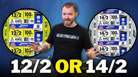
Should You Be ONLY Using 12/2? When Can You Use 14/2?
Join this channel to get access to perks:
https://www.youtube.com/channel/UCB3jUEyCLRbCw7QED0vnXYg/join
When it comes to using NM cable to wire a house, there are 2 general camps that contractors fall into. Those that wire the house in 14/2 and those that will wire the house entirely in 12/2. But which is the correct way to do it? In today’s episode of Electrician U, Dustin dives into this topic and gives us some explanations and tips on doing it correctly.
🤘⚡️MEMBERSHIP⚡️🤘
JOIN ELECTRICIAN U - become a member and get:
FREE Continuing Education every year
FREE Practice Exams
FREE Monthly Video Courses
FREE Weekly Live Instructor-Led Classes
FREE Monthly Educational Newsletter
Premium Members-Only Content
Private Discord Channel
Monthly Members-Only Discord Chats
Sign up here --- https://www.electricianu.com/electrician-u-membership/
🎧🎹MUSIC AND VIDEO:🎹🎧
https://www.facebook.com/descantmv
🎬✍️ART AND ILLUSTRATION:✍️🎬
https://www.daverussoart.com
So, the initial response to this question is to check with your Local AHJ (electrical inspector) to find out their requirements and the requirements of the jurisdiction you are working in. The inspector will have the final say of what they are willing to inspect. The current electrical code (2023 NEC is the most recent, however, many jurisdictions are still using the 2020 NEC) is also a resource to be referenced. Articles 240.4, 210.21 and 310.16 are great articles governing circuitry and wire sizing. Something to keep in mind is that type NM cable falls under the 60-degree rating, and not the 75-degree rating used in most commercial wiring.
The next, and most practical, explanation of what to use to wire a house would be the circuitry type itself. In recent discussions on Electrician U, we have covered Series wiring and Parallel wiring. From those discussions, we have deduced that (for amperage) on a series circuit, amperage is the total of ALL the loads, and that amperage is throughout the entire circuit. This is because we must travel THROUGH one load to get to the next load. But, on a parallel circuit, the amperage is in direct relation to the resistance of the particular load within each leg, and the combined amperage of everything that is on the entire circuit is only on the conductors that are feeding. This is where we will focus on some options we have (again, depending on what our local AHJ will accept).
LED lighting draws considerably less amperage than its incandescent/fluorescent counterparts. So, while installing 12/2 NM cable from the panel throughout the power portion of the circuit, once we leave the load side of the switch, that can be run in 14/2 since amperage draw is less. Consider this circuit- let’s say we have a parallel circuit with one receptacle feeding a 5a load, a second circuit feeding an 8a load, a light switch that was controlling 4 LED can lights at 1a, and a 3rd receptacle at the end completing our circuit. With the first 5a load running, the amperage draw would be 5a from the breaker through our load. Once we started our second 8a load, the conductors around that load would be drawing 8a but where they enter the circuit conductors “feeding” the other loads, the amperage draw is 13a. If we added the 4 can lights, those feeding conductors are drawing 14a now, but those on the load side of the switch are only drawing 1a! So, as long as the local AHJ accepts it, many contractors will run 12/2 conductors throughout the receptacle circuit and up to the line side of the switch, and swap over to 14/2 for the load side of the switch throughout the lighting portion. Over the course of a large home (or many smaller homes added together), the cost/labor savings can be substantial!
We hope this has been helpful in deciding which wire (14/2 or 12/2) to use when wiring a house. Is there a topic you would like to see discussed on Electrician U. Is there a topic you would like to see discussed? Please leave us a comment in the comments section and let us know. Please continue to follow Dustin Stelzer and Electrician U as we are constantly updating our content to assist our followers in becoming the best electricians that they can be.
1.4K
views
2
comments
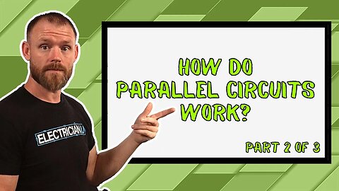
Let's Talk About PARALLEL Circuits: Voltage, Current, Resistance, and Power
Join this channel to get access to perks:
https://www.youtube.com/channel/UCB3jUEyCLRbCw7QED0vnXYg/join
Discovering the difference between Series Circuits, Parallel Circuits, and Combination Series-Parallel Circuits can be confusing for many residential and commercial electricians. In the ongoing series on circuits, Dustin will be talking about Parallel circuits in today’s episode of Electrician U.
🤘⚡️MEMBERSHIP⚡️🤘
JOIN ELECTRICIAN U - become a member and get:
FREE Continuing Education every year
FREE Practice Exams
FREE Monthly Video Courses
FREE Weekly Live Instructor-Led Classes
FREE Monthly Educational Newsletter
Premium Members-Only Content
Private Discord Channel
Monthly Members-Only Discord Chats
Sign up here --- https://www.electricianu.com/electrician-u-membership/
🎧🎹MUSIC AND VIDEO:🎹🎧
https://www.facebook.com/descantmv
🎬✍️ART AND ILLUSTRATION:✍️🎬
https://www.daverussoart.com
Try to think of a parallel circuit having the power source hit all the loads at once as opposed to a series circuit, where you must travel THROUGH one circuit to get to the next. There are also a few things that are different when it comes to the calculations between series circuits and parallel circuits. In a series circuit, voltage is dropped off at each load. In a parallel circuit the voltage is constant throughout the circuit. Current in a series circuit is constant throughout the circuit whereas in a parallel circuit, they are directly proportional to the resistance and additive overall. Resistance in a parallel circuit can be figured by using the inverse of the sum of inverses of each resistance. And lastly, power can be figured by using the formula P= Esquared/Rt.
Let’s try a problem and see if it works! 50v Power source, 2 resistive loads at 2 ohms (R1) and 4 ohms (R2) and R1 amperage is 25a and R2 amperage is 12.5a with an overall amperage of 37.5a. Using ohms law (E=IxR) we can see the following- R1 (25x2) = 50v and R2 (12.5x2) = 50v. Kirchhoff was correct! Amperage once again let’s look to the ohms law formula of I=E/Rn. So, for our first load we have 50v/2ohms = 25a and for our second load we have 50v/4ohms = 12.5a. Once again, the formulas do in fact work! Power is figured using the P=IxE for each load. So, for the R1 load 25 x 50 = 1250w and for the R2 load 12.5 x 50 = 625w. This wattage is also added together to give us an overall wattage of 1875w for the entire circuit.
Since we are dealing with 2 resistances only there are 2 ways to figure this. We can use the inverse of the sum of inverses mentioned above. So, 1/ (1/R1 + 1/R2) = 1/ (1/2 + ¼) = 1/.75 or 1.3 ohms of resistance. The other way (since we have only 2 resistances, it won’t work for any more than that) we can use the product over sum method (it’s a bit simpler!). This formula is Rt = R1xR2/R1+R2. So, for our problem that would be 2x4/2+4= 8/6 or 1.3 ohms.
So much like Series Circuits, we can see that Kirchhoff’s laws concerning Parallel Circuits are in fact correct. Now that we know the formulas for both series and parallel circuits, and have in fact proven them to be correct, it will make it much easier to understand combination circuits, which have elements of both Series and Parallel circuits.
We hope this has been helpful in understanding parallel circuits. Is there a topic you would like to see discussed on Electrician U? Leave us a comment in the comments section and let us know. Please continue to follow Dustin and Electrician U as we are constantly updating our content to assist our followers in becoming the best electricians that they can be.
943
views
2
comments

What is Your Opinion? Here's Your Chance to Make a Difference!
Join this channel to get access to perks:
https://www.youtube.com/channel/UCB3jUEyCLRbCw7QED0vnXYg/join
Here at Electrician U, we certainly value our followers’ opinions on what we put out there for yall to visually & audibly consume. In today’s episode of Electrician U, Dustin is asking for everyone’s opinion on the video backdrop for the new studio.
🤘⚡️MEMBERSHIP⚡️🤘
JOIN ELECTRICIAN U - become a member and get:
FREE Continuing Education every year
FREE Practice Exams
FREE Monthly Video Courses
FREE Weekly Live Instructor-Led Classes
FREE Monthly Educational Newsletter
Premium Members-Only Content
Private Discord Channel
Monthly Members-Only Discord Chats
Sign up here --- https://www.electricianu.com/electrician-u-membership/
🎧🎹MUSIC AND VIDEO:🎹🎧
https://www.facebook.com/descantmv
🎬✍️ART AND ILLUSTRATION:✍️🎬
https://www.daverussoart.com
As most of you know, Dustin and Electrician U are going to soon be moving the operation to Massachusetts (which yall have given a whole range of thoughts & emotions on that!). An entirely new studio will be built with some office space for the logistical side of things, a new podcast studio, an electrical training area, and a new video filming studio as well. Exciting times folks, exciting times!
So, to the point then. We are asking about the background for the videos. Should we keep it the same with the wood panels, metal panels, old electrical equipment/components, and books or should we do something new? Maybe current electrical stuff on the wall, or maybe some different lighting coloring/types or some type of crazy/funky lighting? Maybe the logo on the wall itself? Please leave us some comments in the comments section and let us know your thoughts. We do read them! If there are any of yall that have something you think is worth putting on display, please email Support@electricianu.com. Let’s have a conversation and see what we can come up with. Please continue to follow Dustin and Electrician U as we are constantly updating our content to assist our followers in becoming the best electricians that they can be.
549
views

Do We Need Separate Ground Rods for Each Sub Panel?
Join this channel to get access to perks:
https://www.youtube.com/channel/UCB3jUEyCLRbCw7QED0vnXYg/join
For us electricians that have been doing electrical work for any length of time, we know that we are to put a ground rod (or series of them) at the service panel/point. But can we put them at each additional sub panel, and should we? In today’s episode of Electrician U, Dustin brings some clarity to this topic.
🤘⚡️MEMBERSHIP⚡️🤘
JOIN ELECTRICIAN U - become a member and get:
FREE Continuing Education every year
FREE Practice Exams
FREE Monthly Video Courses
FREE Weekly Live Instructor-Led Classes
FREE Monthly Educational Newsletter
Premium Members-Only Content
Private Discord Channel
Monthly Members-Only Discord Chats
Sign up here --- https://www.electricianu.com/electrician-u-membership/
🎧🎹MUSIC AND VIDEO:🎹🎧
https://www.facebook.com/descantmv
🎬✍️ART AND ILLUSTRATION:✍️🎬
https://www.daverussoart.com
The easiest answer to the question is yes! Article 250 of the NEC does NOT disallow putting additional ground rods at each sub panel. You could put several at each one, provided that they are 6 feet apart from one another. And in some locations around the country, additional ground rods may even be needed if the resistance from one ground rod is not enough. But in order to answer the question fully, let’s talk a bit about the neutral/ground bond first.
The neutral is bonded to the ground at our main service panel, and this is done for a very good reason. As current needs a complete loop to work, this bond is necessary if something goes awry in the system, it provides a complete loop back to source so the breaker (or fuse) can do its job and trip. If the neutral and ground weren’t bonded together, there is a chance that the errant electrical energy could be present in areas that we don’t want it in, causing damage to property and person, while the breaker doesn’t sense anything. The amount of amperage sensed in this scenario (due to the resistance of the ground) is so high, the breaker has no alternative other than to trip. And that’s the point!
So, knowing now that this neutral/ground bond in the service panel is a good thing, why then don’t we do it at every sub panel? Well, if we did, that would give that errant electrical energy MORE than one path to get back to ground, and we would have a real mess in more than one area. As ALL the grounds and ALL the neutrals are joined together (separately) at each sub panel, and if the neutral and ground were bonded together at each sub panel, then you can see the number of places that that errant energy would be allowed to go! So, we keep it to the service entrance only, leaving only one path to return to source.
We DO have to run an Equipment Grounding Conductor to each separate sub panel, and these are all linked together as part of our grounding system. This keeps all metal (conductive objects) within the electrical system effectively linked together. Again, without this, objectionable current could be allowed into places we don’t want it to go.
One important thing to remember is, the NEC is a document of minimums and maximums. The items discussed are the bare minimum requirements that the Code requires for the safety of property and person. If you want to go above and beyond, you are more than welcome to do so. In fact, many of us commercial electricians, electrical contractors, and wiremen do. If we do, we still must adhere to the Code as to how, and we CAN’T install LESS than the code allows.
We hope this has been an informative look into the use of ground rods at panels and the usage of the neutral/ground bond. Is there a topic you would like to see discussed on Electrician U? Please leave us a comment in the comments section and let us know. Please continue to follow Dustin and Electrician U as we are constantly updating our content to assist our followers in becoming the best electricians that they can be.
#electrician #electrical #electricity #do #we #need #seperate #ground #rods #each #sub #panel
1.03K
views
1
comment

To Twist or not To Twist? THAT is the Question.
Join this channel to get access to perks:
https://www.youtube.com/channel/UCB3jUEyCLRbCw7QED0vnXYg/join
Pre-twisting your joints under a wire nut has been and continues to be an ongoing debate amongst most electricians for years. Some tradesmen do and some don’t. So, which is the correct way to do it? In today’s episode of Electrician U, Dustin sheds some light on the subject.
🤘⚡️MEMBERSHIP⚡️🤘
JOIN ELECTRICIAN U - become a member and get:
FREE Continuing Education every year
FREE Practice Exams
FREE Monthly Video Courses
FREE Weekly Live Instructor-Led Classes
FREE Monthly Educational Newsletter
Premium Members-Only Content
Private Discord Channel
Monthly Members-Only Discord Chats
Sign up here --- https://www.electricianu.com/electrician-u-membership/
🎧🎹MUSIC AND VIDEO:🎹🎧
https://www.facebook.com/descantmv
🎬✍️ART AND ILLUSTRATION:✍️🎬
https://www.daverussoart.com
The topic of pre-twisting your wires prior to putting a wire connector on has been one of the most widely debated practices in the electrical industry. And it continues to be one to this day! On one half of the divide are the tradesmen/electrical contractors that say that pre-twisting your wires will make a solid connection even when the wire connector is removed. On the other half of the fence are the tradesmen/electrical contractors that say pre-twisting your wires is a complete waste of time. With 2 clear lines drawn in the sand, how do we know which is actually the proper way to make up our wires?
To start the debate, let’s talk about the wire connectors themselves. Wire connectors of past years were not made the same as they are today. I think we have all been there- out on a service call trying to troubleshoot something only to find that there was an old wirenut that had loose conductors within it that dropped power to some device. Expansion and contraction of the wire from being energized/deenergized, stuff being plugged in and out could have the wires worked loose if you didn’t twist them together really well. But todays wirenuts will actually twist the wires much better than the old ones did. You can strip your wires, put the wirenut on, and when you remove it, your wires will be reasonably twisted together. Today also, we use a lot of pressure type wire connectors (push in type) that actually do not spin the wires at all.
On the other hand, as we have all been there too, trying to add or rework something where someone had twisted the wires together can be a time-consuming process. Having to untwist the wire bundle to add or remove a conductor and then having to straighten all the stripped wire out can be a royal pain! And again, many wire connections today rely on pressure type connectors and not a twist-on type wire connector and require no twisting at all, which results in a much faster installation.
In the end, it comes down to personal (or corporate) preference. Many of us become very proficient at the art of twisting the wires and the amount of time added is negligible when compared to the solid connection we get. Follow the manufacturer’s instructions for the specific type of wire connector you are using also. If the instructions tell you to pre-twist the wires, then pre-twist them. If it does not specifically tell you, then do what you, as a professional tradesman, feel gives you the most solid connection. The end result should be a joint that won't unintentionally come apart and will stay a solid connection.
We hope this has been an insightful look into the argument of whether to pre-twist your wires or not to pre-twist your wires. Is there a topic you would like to see discussed on Electrician U? Leave us a comment in the comments section and let us know. Please continue to follow Dustin and Electrician U as we are constantly updating our content to assist our followers in becoming the best electricians that they can be.
#electrician #electrical #electricity #twist #wirenuts
1.38K
views
6
comments
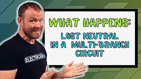
NOT SAFE? Losing a Neutral in a Multiwire-Branch Circuit
Join this channel to get access to perks:
https://www.youtube.com/channel/UCB3jUEyCLRbCw7QED0vnXYg/join
Have you ever wondered what would happen if you removed the neutral wire on a multiwire branch circuit? Would it be as simple as your toaster not working or would it be something much worse? In today’s episode of Electrician U, Dustin explains what would happen if you did.
🤘⚡️MEMBERSHIP⚡️🤘
JOIN ELECTRICIAN U - become a member and get:
FREE Continuing Education every year
FREE Practice Exams
FREE Monthly Video Courses
FREE Weekly Live Instructor-Led Classes
FREE Monthly Educational Newsletter
Premium Members-Only Content
Private Discord Channel
Monthly Members-Only Discord Chats
Sign up here --- https://www.electricianu.com/electrician-u-membership/
🎧🎹MUSIC AND VIDEO:🎹🎧
https://www.facebook.com/descantmv
🎬✍️ART AND ILLUSTRATION:✍️🎬
https://www.daverussoart.com
In a normal 120v branch circuit, I think we all know what would happen if we removed the neutral from the circuit. Since current flow needs a complete path from source, through the load, and back to source, the circuit would NOT function if the neutral was removed. It’s also helpful to understand that the neutral conductor carries the full load of the circuit in a normal branch circuit.
On a multiwire branch circuit things are very different. A multiwire branch circuit is where you have multiple phase (hot) conductors that share a common neutral. The neutral conductor carries only the unbalanced load between the 2 loads. There are rare cases where the 2 circuits are drawing the EXACT same amperage and the neutral conductor has ZERO load on it, but again usually NOT the case. If you were to remove the neutral conductor on a completely balanced set of devices in a multiwire branch circuit, you are in essence adding the loads together in series. Yes you have double the voltage, but keep in mind that you have double the resistance working against it. Actually, things would function as normal.
But if the loads were unbalanced (as they almost always are) things could get ugly! Let’s say we had an 1800w toaster on one 120v circuit (1800w, 15a, 120v) and a 600w TV on the other (600w, 5a, 120v). The neutral conductor carries the unbalanced load between the two, so it would carry 10a and everything functions normally. If you were to take that neutral away, you would in essence have a complete 240v circuit with 2 different sets of loads in series. The resistances would need to be added together (as is the case in series circuits) which for our example would wind up being 32 ohms. Dividing the voltage (240v) by the 32 ohms we would end up with 7.5 amps (and in series circuits, amperage is equal among the loads). Again, it is helpful to understand that in series circuits, amperages are added together to make up the total amperage of the circuit (for our case it is 240v with the neutral removed).
So, taking the 7.5 amps and applying the INDIVIDUAL resistance to the equation, we can start to see how damaging removing the neutral would be. Our 1800w toaster now is operating on 60 volts (7.5 x 8 ohms of resistance) and our 600w TV is operating on 180 volts (7.5 x 24 ohms of resistance). The toaster is not receiving the proper voltage to generate the 1800 watts of heat so it would not get very hot and is under performing. BUT, the TV is operating at much higher voltage than it is designed for and will most likely be damaged as the circuit boards would probably fry, things may melt, etc. Using the power wheel equations we can finish painting the picture of what our equipment is actually doing. Our 1800w toaster is now consuming less than a third of what its supposed to at 450w (60v squared divided by 8 ohms of resistance) and our 600w TV is consuming more than double of what it is designed to at 1350w (180v squared divided by 24 ohms of resistance). While the toaster is not suffering quite as much damage as our TV (again, the toaster will not get hot and may not last as long as it’s struggling to produce the heat without enough resources to do so), the TV will burn up quickly as it’s being pushed entirely too hard!
We hope this has been helpful in understanding the loss of the neutral conductor on a multiwire branch circuit. Is there a topic you would like to see discussed on Electrician U? Leave us a comment in the comments section and let us know. Please continue to follow Dustin Stelzer and Electrician U as we are constantly updating our content to assist our followers in becoming the best electricians that they can be.
#electrician #electrical #electricity #not #safe #losing #a #neutral #in #multi #branch #circuit
1.16K
views
3
comments
Electrician U Studios Is MOVING TO MASS!
Join this channel to get access to perks:
https://www.youtube.com/channel/UCB3jUEyCLRbCw7QED0vnXYg/join
Electrician U is moving to Massachusetts! Over the next couple of months, Electrician U will be renovating a new space and moving from Texas! In todays Episode, Dustin walks thru the new space and talks a bit about his ideas as to what it will look like. Not that there is anything wrong with Texas (ok, so I may be a bit biased!), but moving to Mass just made sense. The editing team and videographer are there already and a change of scenery would be good. The content we will be producing will be just as awesome and new episodes just as frequent, not to worry.
🤘⚡️MEMBERSHIP⚡️🤘
JOIN ELECTRICIAN U - become a member and get:
FREE Continuing Education every year
FREE Practice Exams
FREE Monthly Video Courses
FREE Weekly Live Instructor-Led Classes
FREE Monthly Educational Newsletter
Premium Members-Only Content
Private Discord Channel
Monthly Members-Only Discord Chats
Sign up here --- https://www.electricianu.com/electrician-u-membership/
🎧🎹MUSIC AND VIDEO:🎹🎧
https://www.facebook.com/descantmv
🎬✍️ART AND ILLUSTRATION:✍️🎬
https://www.daverussoart.com
So, the first thing that needed to be done was get the existing tenants stuff moved out of the space into a new one. Then the fun begins! The demising wall had to be reframed and sound proofing added. This was done with several layers of drywall and some foam insulation sheets. This will keep the noise away from the recording area. The old 8’ T12 fluorescent fixtures will be demoed and new can lights will be put in. A green screen wall will be added to help with the editing process as well.
An instructional area will be built as well and will actually be several different spaces. There will be an area to show the commercial side of things- metal studs, metal boxes, conduit bending, MC cable installations, etc. There will be a residential area that will be comprised of wood studs so the plastic boxes and Romex cable installations can be explained as well. The area that we are used to seeing Dustin talk in front of the camera will change slightly. In lieu of standing in front of the wood/metal walls surrounded by books and electrical apparatus, the camera will be more corner focused and will lend towards a new and improved view.
The aesthetics will also change a bit. We are in talks with a neon sign maker that will be making an Electrician U neon sign that looks like the logo! Super cool!! Dustin is thinking of using a video game type theme, but with an electrical twist. Pikachu, Tron, Thor, anything with electricity in it will adorn the walls. This last part Dustin would like the help of the audience to give some ideas! So make sure and leave some comments in the comments section and let us know what you think!
Needless to say, we are all super pumped and excited about the changes and the upcoming move. There will be growing pains for sure, but well worth it once we get there. We hope you have enjoyed this look into the new space in our new location. Is there a topic you would like to see discussed on Electrician U? Leave us a comment in the comments section and let us know. Please continue to follow Dustin and Electrician U as we are constantly updating our content to assist our followers in becoming the best electricians that they can be.
#electrician #electrical #electricity #electricianu #is #moving #to #mass
1.14K
views
4
comments
What is Electricity? Is There An Answer? #shorts
There's so many conflicting definitions of electricity. Essentially its the relationship between charged particles. What's your definition?
Listen to Sparky Life podcast here:
https://spotify.link/renfKSEyxyb
Sparky Life Youtube Channel
https://youtube.com/@sparkylifeoflia
@sparkylifeoflia
TikTok:
https://www.tiktok.com/@electricianu
Discord:
https://discord.gg/electricianu
Instagram:
https://www.instagram.com/electrician_u
Facebook:
https://m.facebook.com/groups/electricianu/?ref=share&mibextid=zoDNOU
Join Electrician U Membership:
https://www.youtube.com/redirect?event=video_description&redir_token=QUFFLUhqbVYwMlFXUHBDV2psUVc5LVZybHFCZzRKNFRBUXxBQ3Jtc0tuaG40SG5OTDNwcWJrQjlKRExmdno1MUY1TE5udjF0WTIxSHlkMXB5TEJyTTA1TXhBTGNVcTY0eEdGR21iZjJkTkZWdFlZc3p3blpUaG9ESmFEOEZUaGZPTElsZWdxYlV5NUNDS0sxME9wa2hZbklUaw&q=https%3A%2F%2Fwww.electricianu.com%2Felectrician-u-membership%2F&v=I65HCmf8de0
799
views
4
comments
Keep Your Materials Organized! #shorts
Be a more efficient Job Lead
Watch full video here:
https://youtu.be/I65HCmf8de0
TikTok:
https://www.tiktok.com/@electricianu
Discord:
https://discord.gg/electricianu
Instagram:
https://www.instagram.com/electrician_u
Facebook:
https://m.facebook.com/groups/electricianu/?ref=share&mibextid=zoDNOU
Join Electrician U Membership:
https://www.youtube.com/redirect?event=video_description&redir_token=QUFFLUhqbVYwMlFXUHBDV2psUVc5LVZybHFCZzRKNFRBUXxBQ3Jtc0tuaG40SG5OTDNwcWJrQjlKRExmdno1MUY1TE5udjF0WTIxSHlkMXB5TEJyTTA1TXhBTGNVcTY0eEdGR21iZjJkTkZWdFlZc3p3blpUaG9ESmFEOEZUaGZPTElsZWdxYlV5NUNDS0sxME9wa2hZbklUaw&q=https%3A%2F%2Fwww.electricianu.com%2Felectrician-u-membership%2F&v=I65HCmf8de0
666
views

6 Methods For Running Jobs Efficiently
Join this channel to get access to perks:
https://www.youtube.com/channel/UCB3jUEyCLRbCw7QED0vnXYg/join
Many of us electricians aspire to be great at running jobs efficiently. Some of us are just thrown into the position of running jobs and don’t have the knowledge yet on HOW to be great at it. In todays episode of Electrician U, Dustin shares with us 6 ways to be efficient at running work.
🤘⚡️MEMBERSHIP⚡️🤘
JOIN ELECTRICIAN U - become a member and get:
FREE Continuing Education every year
FREE Practice Exams
FREE Monthly Video Courses
FREE Weekly Live Instructor-Led Classes
FREE Monthly Educational Newsletter
Premium Members-Only Content
Private Discord Channel
Monthly Members-Only Discord Chats
Sign up here --- https://www.electricianu.com/electrician-u-membership/
🎧🎹MUSIC AND VIDEO:🎹🎧
https://www.facebook.com/descantmv
🎬✍️ART AND ILLUSTRATION:✍️🎬
https://www.daverussoart.com
1. Keep your materials tracked and organized. Try to place the materials for the jobsite close to where the work will be performed. Putting them in an area that is not directly being worked in (by your crew AND other trades) is helpful so you don’t spend time moving them back and forth. If you are in warmer/sunnier climates, keep in mind that anything stored outside will become scorching hot- so maybe in the shade if possible.
2. Keep good notes. These can be kept ON the drawings (if you have these on the job), but notebooks are also helpful in organizing your notes. Using colored pencils/highlighters helps identify different facets of the work and can be helpful in determining what is completed versus what is still needing to be finished. You should keep running lists of the materials that are needed, questions that have arisen during construction, to do lists, and maybe even lists of which workers you want doing certain tasks so when they complete one task, the next one is available to be started.
3. Walk the job before work starts and at the end of the day. Walking the project before the work crews start will allow you to plan the days activities without being inundated with questions from the crew. Walking the project at the end of the day while everyone is cleaning up will let you check the work done (and you do need to check EVERYONES!) and see which areas still need attention. You still need to be present DURING the day also, but before/after shift just gives you time to actually look in depth with less interruptions.
4. Keep materials stocked in your van/truck. The supply house may NOT be close to you so having extras is important as you cant plan for everything every time. And if you (or someone) had to leave the job to run back and forth to the supply house is just wasting hours when they could be using those hours to actually put in the work. Try to keep a few of the most common items you use on projects on the van (in some type of orderly fashion so you know what you have). Receptacles, wire, boxes, wire connectors, etc.
5. Keep everyone on the jobsite working and productive. Its your job to keep everyone busy- you may not be able to wear your tools because you are constantly moving around keeping everyone supplied with tools/materials/knowledge/answers to questions. This is perfectly acceptable and a requirement of the job. The electricians underneath you NEED to learn how to put in the work, so if you are the one constantly doing the work, how would they get the experience.
6. Learn to shift gears. Some jobs have the $$ built in to allow us to take extra time and make it look really good. Some jobs do not have that. Learning when to apply each working style is important. There is a fine line between quality and speed and can be a balancing act at times. Put in the work properly every time, but know when to spend extra making it look really good versus installing as fast as you can install it.
We hope these 6 tips have been helpful in understanding some of the things it takes to run an efficient jobsite. Is there a topic you would like to see discussed on Electrician U? Leave us a comment in the comments section and let us know. Please continue to follow Dustin and Electrician U as we are constantly updated to assist our followers in becoming the best electricians that they can be.
#electrician #electrical #electricity #six #methods #for #running #jobs #efficiently
816
views

Why Do You Use So Many Types of Screws?
Join this channel to get access to perks:
https://www.youtube.com/channel/UCB3jUEyCLRbCw7QED0vnXYg/join
Sheetrock screws, Self-Tapping screws, Phillips screws, Panhead screws- Have you ever wondered why there are so many types of screws available? In todays episode of Electrician U, Dustin talks about a few of the most popular types of screws and what their uses are for.
🤘⚡️MEMBERSHIP⚡️🤘
JOIN ELECTRICIAN U - become a member and get:
FREE Continuing Education every year
FREE Practice Exams
FREE Monthly Video Courses
FREE Weekly Live Instructor-Led Classes
FREE Monthly Educational Newsletter
Premium Members-Only Content
Private Discord Channel
Monthly Members-Only Discord Chats
Sign up here --- https://www.electricianu.com/electrician-u-membership/
🎧🎹MUSIC AND VIDEO:🎹🎧
https://www.facebook.com/descantmv
🎬✍️ART AND ILLUSTRATION:✍️🎬
https://www.daverussoart.com
Let’s talk about the most popular screw heads first. Those are Phillips head and Slotted head screws. These are the oldest and easiest to produce so they tend to be the most popular. Originally designed to be used with screwdrivers (one of the tools an electrician ALWAYS has on hand- pun definitely intended!!). However, with the advent of electrical drills, and in more recent years cordless impact drills, they can be prone to stripping out of the heads if too much torque or speed is applied during the installation process. Still, you can find these types of heads in every screw type available- from metal, to wood, to concrete.
The Robertson head screw was developed to combat the inherent design flaw of the Phillips and Flathead screw heads of stripping out due to speed/torque during installation time. The recessed portion of the head is square and offers much more surface area and they tend to blow out less (although not completely impervious to it!). Allen and Torx head screws are also much better at not stripping out during installation and are very popular in todays screws as well. Pro Tip- if you are using an Allen headed screw and it has blown out, try using a Torx head tip to back it out. It is relatively close in shape and the points on the Torx tip will dig into the wallowed-out sides of a blown out Allen head screw. You can usually remove the damaged screw in this fashion and replace it with a new one. Pan-head screws offer a smooth rounded finish that doesn’t tend to snag on things after its installed. Hex head screws are also popular. You can find these in the fine coarse machine type screws as well as their coarser threaded cousins usually found in wood screws.
The screw shaft can also be found in different flavors as well. You have fine coarse thread machine type screws for metal work. An example of this would be the 6-32 screw us electricians use to install devices. The 6 portion of the screw designation is telling us it is 6 gauge (how thick the shaft is) and the 32 portion is referring to how many screw threads per inch. These types of screws are meant to be installed in metal, through a hole that you drill (slightly smaller than the screw shaft itself) and tap to the screw thread dimension.
The main difference between wood screws/sheet metal screws and machine screws are the threads. While machine screws are fine thread, wood/sheet metal screws are much coarsely threaded and rely on the wide threads to apply the holding pressure to the material. They do come in many of the head types we mentioned above. There are bolts also to consider in our travel through screw types. The difference between screws and bolts is generally diameter. Bolts usually have a much larger diameter and are usually finer thread. Wood lag bolts are the exception to this rule- they still are made in a larger shaft than most wood screws but share the same coarse threads. Lag bolts are meant to hold something that weighs a lot to the woods surface. Carriage bolts are also in the bolt family. The interesting thing about them is that they lack a head you can put a tool on and are meant to be fastened/tightened with a nut on the end. When you tighten the nut against the opposite side of the head, it brings the shoulder of the screw into the material holding it tight.
It is good to keep a selection of machine screws and wood screws available to work with in varying lengths, head types, and diameters. Make sure to have on hand a good selection of washers and nuts to go along with them. Many manufacturers make kits you can purchase with common sizes/lengths so you do not have to buy them all individually.
We hope this has been helpful in understanding some of the many screw types available to electricians. Is there a topic you would like to see discussed? Leave us a comment in the comments section and let us know. Please continue to follow Dustin and Electrician U as we are constantly updating our content to assist our followers in becoming the best electricians that they can be.
#electrician #electrical #electricity #why #are #there #so #many #types #of #screws
1.64K
views

Are You an Electrician? These are 5 Formulas You Should Know!
Join this channel to get access to perks:
https://www.youtube.com/channel/UCB3jUEyCLRbCw7QED0vnXYg/join
Being a great electrician requires a strong knowledge of math. We use it daily from bending conduit, to figuring out what wire to pull, even simply counting light fixtures or circuits. But which formulas should we be more familiar with? In todays episode of Electrician U, Dustin explains the top 5 formulas every electrician should know.
🤘⚡️MEMBERSHIP⚡️🤘
JOIN ELECTRICIAN U - become a member and get:
FREE Continuing Education every year
FREE Practice Exams
FREE Monthly Video Courses
FREE Weekly Live Instructor-Led Classes
FREE Monthly Educational Newsletter
Premium Members-Only Content
Private Discord Channel
Monthly Members-Only Discord Chats
Sign up here --- https://www.electricianu.com/electrician-u-membership/
🎧🎹MUSIC AND VIDEO:🎹🎧
https://www.facebook.com/descantmv
🎬✍️ART AND ILLUSTRATION:✍️🎬
https://www.daverussoart.com
First on the list is Ohms law. This formula is the relationship between Voltage, Amperage, and Resistance. In many cases, we are not given ALL of the information for a piece of equipment, but still need to determine either the voltage or amperage of it. Ohms law is simply E (voltage) over I (amperage) times R (resistance). So, draw a circle and put a large T in the center of it. Above the horizontal line of the T draw an E. On the left of the vertical line draw an I and on the right of the line draw an R. To assist you, cover up the letter you are attempting to solve. For instance, if I covered up E (voltage) it would leave me with I (amperage) multiplied by R (resistance). If I had a 20a piece of equipment with a 6 ohm resistance (20 x 6) it would be running at 120v!
The next formula is Joules law. This one is slightly different than Ohms law and is the relationship between Wattage, Amperage, and Voltage. The circle is the same as above but with a P on top, an I on the left, and an E on the right. The math is the same also. So, if I was attempting to see how many watts were on a given circuit, cover up the P and I am left with I (amperage) times E (voltage). For a 20a circuit operating at 120v, I would have 2400w. Both of these formulas are very useful because we don’t always get all of the information we need on the equipment nameplate.
Voltage Drop is something that every electrician should know how to figure out. For a single phase circuit the formula is 2 x K(conductor) x I (circuit amperage) x L (length) divided by the circular mils of the conductor you are attempting to use. For 3 phase replace the 2 with a 1.732 (the square root of 3). If you have a copper conductor use 12.9 and use 21.2 if you are using aluminum conductors. The circular mils for electrical conductors can be found in the NEC codebook in Chapter 9 Table 8. The resulting number after crunching the equation is the amount of volts that are lost. You may find that you may need to upsize your wire (and perhaps the conduit) to get your voltage drop down to a reasonable level.
Resistance formulas are needed for every electrical theory class! For a series circuit the total resistance is the sum of all the resistances. For a parallel circuit, it’s the reciprocal of the sum of all the reciprocals. So, 1 divided by 1/R1 + 1/R2 + 1/R3 + etc. An easier way for that last one would be product over sum formula. So, if you had a parallel circuit with resistances of 2, 3, & 4 the formula would be 2 x 3 x 4 divided by 2 + 3 + 4. Much Simpler!
Lastly is Horsepower. Something to just keep in mind is that 1 HP is equivalent to 746 watts. For single phase motors the formula is HP= E (voltage) x I (amperage) x EFF (efficiency) x PF (power factor) divided by 746. For a 3 phase motor, simply insert 1.732 (the square root of 3) in front of the E. Efficiency you can find on the nameplate of the motor. If you have a completely balanced load that isn’t running a ton of motors you may have a power factor of close to 1. The more motors you have on any given system, that number goes down (say to .7 or even more).
We hope this has been helpful in understanding the 5 most popular formulas an electrician uses frequently. Is there a topic you would like to see discussed on Electrician U? Leave us a comment in the comments section and let us know. Please continue to follow Dustin and Electrician U as we are constantly updating our content to assist our followers in becoming the best electricians that they can be.
#electrician #electrical #electricity #these #are #five #formulas #you #should #know
1.8K
views
5
comments

The WORST SHOCK I Have Ever Received!!!
Join this channel to get access to perks:
https://www.youtube.com/channel/UCB3jUEyCLRbCw7QED0vnXYg/join
Of all the things us electricians do daily that can get us hurt, or worse, getting shocked is at the top of the list. In today’s episode, Dustin tells us about his worst experience with getting shocked and also shares a few tidbits of information that can help us understand WHY we get shocked & how to not let that happen.
🤘⚡️MEMBERSHIP⚡️🤘
JOIN ELECTRICIAN U - become a member and get:
FREE Continuing Education every year
FREE Practice Exams
FREE Monthly Video Courses
FREE Weekly Live Instructor-Led Classes
FREE Monthly Educational Newsletter
Premium Members-Only Content
Private Discord Channel
Monthly Members-Only Discord Chats
Sign up here --- https://www.electricianu.com/electrician-u-membership/
🎧🎹MUSIC AND VIDEO:🎹🎧
https://www.facebook.com/descantmv
🎬✍️ART AND ILLUSTRATION:✍️🎬
https://www.daverussoart.com
As with many of us, there are horror stories of the worst shock we received. For Dustin, he was working alone underneath a house, laying on the dirt that was soaked from recent rain, he was working with live circuitry in a j box, and had maybe 3 years in the trade. He tried using a voltage tick tracer to tell him when the circuit was shut off, but it gave a false reading leading him to believe that the circuit was not energized. A wire fell out of the j box, landed on his chest, and since he was in direct contact with the earth, he received a wicked shock. So, how could the incident have been avoided?
In the scheme of things, we should NEVER work on energized circuitry unless it is absolutely necessary (we are troubleshooting & need to have the circuit energized to see what it is/is not doing), we are testing and need the circuit energized to get values, or there is greater damage possible to property/humans well-being AND we have the proper training to work on it. Shutting the circuit off is the best way to avoid a shock. In addition to shutting it off, a proper LOTO (lock out tag out) plan should also be implemented, so there is no possible way that the circuit can be reenergized while we have our hands on it. This could be installing a breaker lock/tag or padlocking/tagging a disconnect in the off position, or something similar. A tip if working on a fused disconnect- take the fuses OUT when working on the circuit (in addition to locking it out) so there is no way that the circuit can make it all the way to you even if the disconnect is unlocked.
Another thing to keep in mind is the way we take care of and use our electrical testing devices (meters, voltage tic sticks, etc.). Do NOT just throw your testing equipment in the back of the truck leaving it susceptible to the elements and damage, throw it into your truck toolbox, or in the gang box and pile other tools on top of it. Our meters could literally be used to protect your life and should be treated as sensitive equipment. They should be kept in a separate box/bag/etc. and cared for. They should be tested fairly frequently on live circuits to check if they are operating properly and the batteries should be replaced on regular intervals. When using a meter (or a hot stick) to see if a circuit is de energized, they should first be checked on a live circuit to verify they are working, THEN check the circuit you are working on, AND then rechecked on a known live circuit. This will ensure your meter is operating properly.
IF working on a live circuit is necessary, a couple of important items should be taken into consideration. Do NOT work it alone with no one around. Make sure that another qualified person is available and knows what you are attempting to do. You should also be properly trained in the working of live circuits so you recognize and avoid the dangers. Proper PPE should also be used and will be task specific. When in doubt, check with your safety representative, your supervisor, or veterans of the trade. Keep in mind that electricity will always look for the shortest path to make a complete circuit, and if you insert yourself into that loop, you are going to receive a nasty surprise. Make sure you are not standing in (or laying on) a puddle of water or saturated soil and make sure your other body parts are not touching anything grounded, a neutral conductor, or another circuit.
We hope this has been helpful in understanding some of the ways you can receive an electrical shock and how to avoid them. At the end of the day, we are working to support ourselves and our families and if we get hurt (or worse) by getting shocked (when it could have been avoided), then we would be working for nothing! Is there a topic you would like to see discussed on Electrician U? Leave us a comment in the comments section and let us know. Please continue to follow Dustin and Electrician U as we are constantly updating our content to assist our followers in becoming the best electricians that they can be.
#electrician #electrical #electricity
1.53K
views
7
comments
What is the Difference Between Grounding, Bonding and Neutral?
Join this channel to get access to perks:
https://www.youtube.com/channel/UCB3jUEyCLRbCw7QED0vnXYg/join
When it comes to terms of the trade, nothing gets more misunderstood or confusing as the terms Grounding, Bonding, and Neutral. They seem to be used interchangeably back and forth and can even confuse many journeymen. In todays episode, Dustin defines these terms and brings some clarity to each one.
🤘⚡️MEMBERSHIP⚡️🤘
JOIN ELECTRICIAN U - become a member and get:
FREE Continuing Education every year
FREE Practice Exams
FREE Monthly Video Courses
FREE Weekly Live Instructor-Led Classes
FREE Monthly Educational Newsletter
Premium Members-Only Content
Private Discord Channel
Monthly Members-Only Discord Chats
Sign up here --- https://www.electricianu.com/electrician-u-membership/
🎧🎹MUSIC AND VIDEO:🎹🎧
https://www.facebook.com/descantmv
🎬✍️ART AND ILLUSTRATION:✍️🎬
https://www.daverussoart.com
First lets understand that while a Neutral is a type of Grounded Conductor but not every Grounded Conductor is a Neutral. A grounded conductor is a conductor that is intentionally brought to ground. So, for most electrical systems, a neutral IS a grounded conductor because it is bonded to ground, but under certain circumstances it doesn’t HAVE to be.
A grounding electrode is something that is in contact with the earth (ground). It could be a ground rod, plate, underground metallic structure, etc. A grounding electrode conductor is a piece of wire (conductor) that connects the grounding electrode to the ground bus within the system. This is separate from the Equipment Grounding conductor. Way back in the electrical trade, grounds were not run with the hots and neutrals that those systems still worked. However, in today’s trade, we generally run grounds with EVERYTHING, so it’s always present.
Let’s talk about Bonding Jumpers. A bond isn’t a neutral or a ground specifically. A bonding jumper connects two metallic pieces of equipment together in essence making one large piece of metal. A Main Bonding Jumper connects our Grounding bus and bonds it to the Neutral bus in our panel. Some panel manufacturers accomplish this by using those large green screws. That screw goes through the bus into the metallic portion of the panel therefore bonding the bus to the can. It can also be accomplished by running a piece of wire in between the ground bus and the neutral bus. The result is the same. If using wire, consult table 250.102(c)(1) in the NEC for sizing. A Supply Side Bonding Jumper connects anything metallic before the main breaker to the grounding system. So, since we don’t run grounds from the utility transformer to our service we have to be able to bond those metal cans with something. Enter the Supply Side Bonding Jumper! Separately derived systems also have a bonding jumper. Since we have bonded the neutral and ground at our service already, what happens at a transformer (say 480-120/208)? That is where the System Bonding Jumper comes in. This connects the XO (neutral in the transformer) to the grounding system (EGC, the transformer casing, etc.). This is also sized using table 250.102(C)(1) of the NEC.
The Equipment Grounding Conductor connects any piece of equipment to the grounding system. Panels, devices, equipment, etc. are all tied together (from a grounding standpoint). The purpose of this is to provide an alternate path to ground (safety) in the event that something happens so that the breaker will open and shut power off to the equipment having issues. Its merely there for safety reasons. Equipment Grounding Conductors can be sized using table 250.122 of the NEC and are based upon size of the breaker feeding the equipment, whereas the Bonding Jumpers sizes are derived using the size of the largest service entrance conductor. An Equipment Bonding Jumper in essence connects 2 pieces of equipment together from a Ground standpoint.
We hope this has been helpful in understanding the differences between Grounding, Bonding, and Neutral. Is there a topic you would like to see discussed on Electrician U? Leave us a comment in the comments section and let us know. Please continue to follow Dustin and Electrician U as we are constantly updating our content to assist our followers in becoming the best electricians that they can be.
#electrician #electrical #electricity #what's #the #difference #between #bonding #grounding #and #neutral
1.99K
views
4
comments
How to Bend an Offset in Conduit
Join this channel to get access to perks:
https://www.youtube.com/channel/UCB3jUEyCLRbCw7QED0vnXYg/join
⚡🔨SPONSOR: PENN ALUMINUM🔨⚡
https://www.pennconduit.com/
When it comes to bending conduit, offsets are a necessary item to know how to bend. But until you get the hang of it (and even afterwards) they can be a bit tricky at times. In todays episode of Electrician U, Dustin walks us thru the process of bending an offset.
🤘⚡️MEMBERSHIP⚡️🤘
JOIN ELECTRICIAN U - become a member and get:
FREE Continuing Education every year
FREE Practice Exams
FREE Monthly Video Courses
FREE Weekly Live Instructor-Led Classes
FREE Monthly Educational Newsletter
Premium Members-Only Content
Private Discord Channel
Monthly Members-Only Discord Chats
Sign up here --- https://www.electricianu.com/electrician-u-membership/
🎧🎹MUSIC AND VIDEO:🎹🎧
https://www.facebook.com/descantmv
🎬✍️ART AND ILLUSTRATION:✍️🎬
https://www.daverussoart.com
Before we get into offset bending basics, lets take a moment to talk about aluminum conduit. Todays sponsor- Penn Aluminum Conduit & EMT- makes some of the best aluminum conduit on the market. But why choose aluminum EMT over steel EMT? Well, its considerably lighter therefore it takes less labor to install and reduces wear and tear on your field staff hauling conduit around. Next, its much easier to bend than steel, again, making it less strenuous on your staff to install and using less labor. Its also cheaper than steel currently, so it helps on the bottom line. Penn Aluminum has even engineered a coating for the inside of the conduit that helps with wire pulling and eliminates the snagging most often associated with aluminum conduit. Give it a shot, I think you will like it!
Onto the bending! An offset is a bend that allows us to change the course of our conduit run. It is a series of 2 opposing bends with a length of straight unbent conduit in between. Maybe we need to clear an object that is in our way or enter a junction box/pull box/panel where the knockout is not lined up exactly in line with our conduit. So, the first thing we need to do is to figure out the distance we need to offset our conduit. Once that is established, we need to figure out how FAST we need to offset our conduit (I am not necessarily talking about the speed in which we work. That is usually fast!!). If we don’t have a lot of space to make the offset, we may need to use a sharper bend, but if distance isn’t really an issue, then a shallower bend may be used. Typically a 30 degree bend is what we use.
For a 30 degree offset, take the measurement you determined in the first step and double it. That is the distance between your bends. So, make a mark on the conduit where you want to start your offset. Then, if you measured a 2 inch obstruction, make a second mark 4 inches away from your first mark. Place the conduit in the bending shoe, with the hook of the bender facing away from you and the arrow on the first mark you made. With the conduit on the ground, apply foot pressure on the shoe AND use arm pressure on the handle to pull back. Most bender handles signify a 30 degree bend when that handle is at 90 degrees to the surface you are bending on.
Once the first bend is complete, roll the conduit (don’t remove it from the bending shoe) 180 degrees. At this point, you will most likely have to invert the bender as your first bend will now be pointing towards the ground. Place the arrow on the second mark and sight down the conduit to make sure your first bend isn’t pointing off to one side or the other (your two bends will need to be in a straight line or you will end up dog legging the bends!). Place your foot in front of the bender so it doesn’t slide on you, place your hands CLOSE to the bender shoe so you don’t bend more of the conduit than necessary, tip the bender slightly forward, and then pull down on the conduit until the bottom of the conduit is in line with the 30 degree line on the bender shoe. Viola! Offset complete!
A couple pro tips. Use a pencil (not a sharpie) to make your marks. That way you can erase it when done bending-looks more professional. Always carry a torpedo level on you when bending conduit- you will need it to be accurate. You can make corrections if you over bend or dog leg the conduit. Practice is needed to get good at bending! As discussed earlier, 30 degrees is the most common bend utilizing a multiplier of 2. For a 45 degree offset (a sharper bend) use a 1.4 multiplier and for a 22-1/2 degree bend (even less drastic than a 30) use a 2.6 multiplier.
We hope this has been helpful in understanding how to bend an offset. Is there a topic you would like to see discussed on Electrician U? Leave us a comment in the comments section and let us know. Please continue to follow Dustin and Electrician U as we are constantly updating our content to assist our followers in becoming the best electricians that they can be.
#electrician #electrical #electricity #how #to #bend #an #offset #in #conduit
862
views
2
comments